Product description, Terminals – Lenze I/O system 1000 System Manual User Manual
Page 157
Product description
I/O compound modules − counter
One counter 32 bits, 24 V DC − EPM−S600
l
157
EDSIO1000 EN 7.0
Messages of the status LEDs RUN and MF
RUN
MF
Meaning
On
Off
Module status OK
Bus communication is OK
On
On
Module reports error
Bus communication is OK
Off
On
Module reports error
Bus communication not possible
Off
Off
Error in the bus supply voltage
Blinking
Blinking
Configuration error (
^ 249)
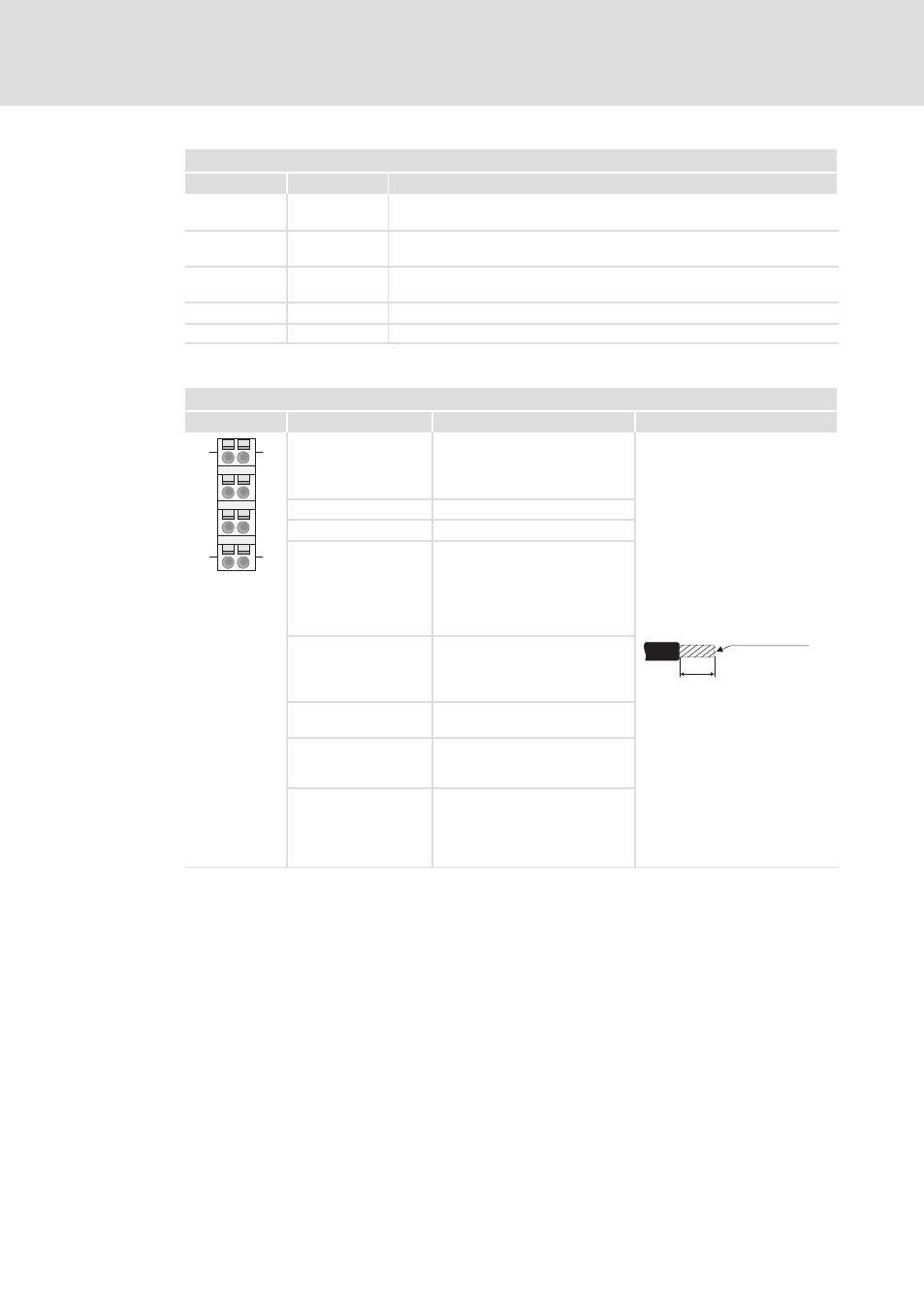
Terminals
Module terminals, spring terminals
1
View
Designation
Explanation
Terminal data
2
6
3
7
4
8
1
5
1
5
4
8
1
Digital input "A"/"pulse"
Pulse input for counting signal or
track A of an encoder for single,
double, or quadruple evaluation
10 mm
0.08 ... 1.5 mm²
(AWG 28 ... 16)
2
DC 24 V for encoder supply
3
GND
4
Digital input "Latch"
With a positive edge or a
level−triggered signal at "Latch",
the current counter content is
stored as latch value in the input
area.
5
Digital input "B"/"direction"
Direction signal or track B of an
encoder (can be inverted via
parameterisation)
6
Digital output "OUT"
(parameterisable)
7
Digital input "Reset"
With a positive edge at this input
the counter is reset.
SLIO002
8
Digital input "Hardware gate"
With a HIGH level at this input
the hardware gate is opened and
the counting process is started
(parameterisable).