4 terminology used, Terminology used, About this documentation – Lenze I/O system 1000 System Manual User Manual
Page 16
About this documentation
Terminology used
l
16
EDSIO1000 EN 7.0
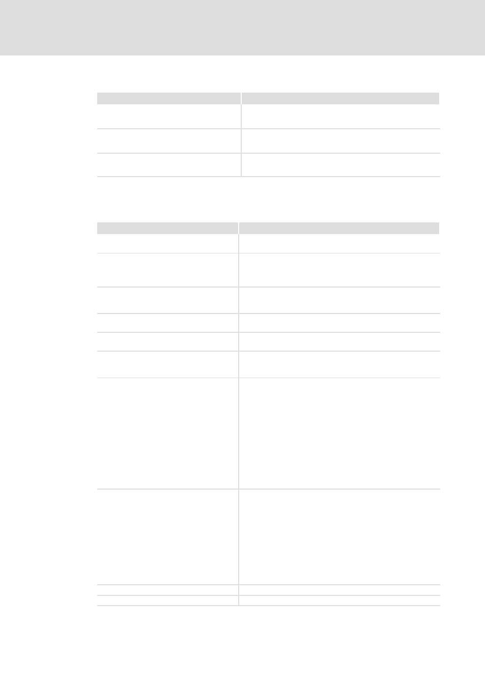
Application notes
Pictograph and signal word
Meaning
)
Note!
Important note to ensure troublefree operation
I
Tip!
Useful tip for simple handling
,
Reference to another documentation
1.4
Terminology used
Term
Meaning
I/O compound module
EPM−S2xx, EPM−S3xx, EPM−S4xx, EPM−S5xx, EPM−S6xx; module
of the I/O system 1000 (DI, DO, AI, AO, counter, etc.)
Bus coupler, bus coupler module
EPM−S1xx; for connection of the I/O system 1000 to a fieldbus
system (CANopen, PROFIBUS, etc.). With an integrated DC power
supply unit (main supply) for supply of the bus coupler module
and the connected I/O compound modules via backplane bus.
Power supply module
EPM−S7xx; additional DC power supply unit that is used in
extensive systems if the main supply of the bus coupler is not
sufficient to supply the I/O level and/or the electronics.
Power distributor module
EPM−S9xx; power distributor for the supply of external
consumers via the I/O system 1000 (24 V and/or 0 V)
Backplane bus
The control signals on the process level are transferred by the I/O
compound modules via the internal backplane bus.
Ohmic load
In the technical data, the load capacity at a constant ohmic load
is often characterised by specifying a maximum output current
at signal "1".
Lamp load
When the lamp load is specified, the fact is taken into account
that an incandescent lamp has the n−fold starting current
compared to the rated current. Only when the glow wire is
heated, the resistance strongly increases. In the data sheets, the
lamp load is characterised by specification of a power in watts
which is considerably lower than the product of the rated voltage
and the permissible output current. The high starting current of
an incandescent lamp is also the reason for the fact that the
maximum switching frequency is lower by a factor of
approximately ten than it would be at a constant ohmic load.
Therefore only incandescent lamps which, in total, do not feature
a higher rated power than specified in the specification of the
lamp load must be connected to a digital output. This does not
concern LED lamps; they are treated as an ohmic load.
Inductive load
In the case of an inductive load, the impedance of the consumer
(relay coil, contactor) depends on the operating frequency of the
digital output. In this case, as well, the permissible switching
frequency is strongly reduced compared to that for a constant
ohmic load, in order to ensure reliable switching of the relay. The
cause of this is the discharge of inductance by the interrupting
current via the suppressor circuit. If the switching frequency is
too high, the interrupting current can no longer decay
sufficiently, so that for instance the relay at the output cannot be
disconnected anymore. Without a suppressor circuit, an
overvoltage at the power transistors of the digital output may
occur, causing damage or destruction of the module.
AI/AO
Analog input/output
DI/DO
Digital input/output