Profibus communication, Diagnostics and alarm – Lenze I/O system 1000 System Manual User Manual
Page 425
PROFIBUS communication
Parameterising the temperature measurement
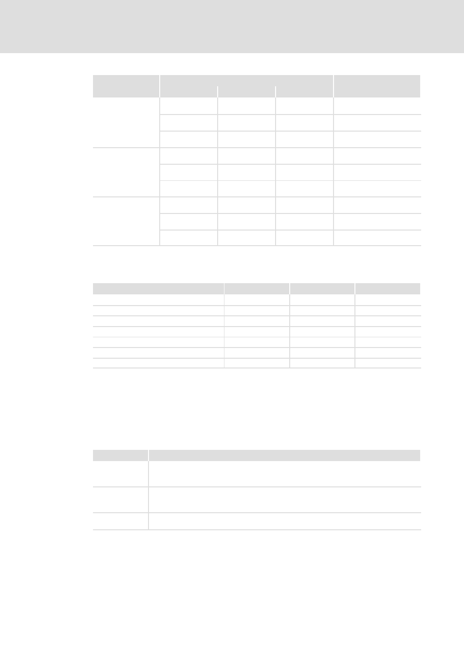
Two analog inputs for thermocouple measurement − EPM−S405
l
425
EDSIO1000 EN 7.0
Range
Measured value
Measuring range
Range
[K]
[°F]
[°C]
(Fct. no.)
Type C:
0 ... +2315 °C
32 ... 2786.5 °F
273.2 ... 2093.2 K
(B7
h
: ext. comp. 0 °C)
(C7
h
: int. comp. 0 °C)
+25000
32766
23432
Overflow
0 ... +23150
320 ... 27865
2732 ... 20932
Nominal range
−1200
−1840
1532
Underflow
Type E:
−270 ... +1000 °C
−454 ... 1832 °F
0 ... 1273.2 K
(B8
h
: ext. comp. 0 °C)
(C8
h
: int. comp. 0 °C)
+12000
21920
14732
Overflow
−2700 ... +10000
−4540 ... 18320
0 ... 12732
Nominal range
−
−
−
Underflow
Type L:
−200 ... +900 °C
−328 ... 1652 °F
73.2 ... 1173.2 K
(B9
h
: ext. comp. 0 °C)
(C9
h
: int. comp. 0 °C)
+11500
21020
14232
Overflow
−2000 ... +9000
−3280 ... 16520
732 ... 11732
Nominal range
−
−
−
Underflow
Diagnostics and alarm
Trigger
Process alarm
Diagnostic alarm
Parameterisable
Configuration/parameterisation error
−
X
−
Open circuit detected
−
X
X
Measuring range exceeded
−
X
−
Measuring range not reached
−
X
−
Limit value exceeded
X
−
X
Limit value not reached
X
−
X
Process alarm lost
−
X
−
Process alarm
A process alarm causes a call of the OB 40. Within the OB 40 you have the possibility of
determining the logic basic address of the module that has triggered the process alarm via
the local word 6. Further information on the triggering event can be found in the "Local
double word 8".
Local double word 8 of OB 40:
Local byte
Bit 7 ... 0
8
Bit 0: Limit value exceeded channel 1
Bit 1: Limit value exceeded channel 2
Bit 7 ... 2: 0 (fixed)
9
Bit 0: Limit value not reached, channel 1
Bit 1: Limit value not reached, channel 2
Bit 7 ... 2: 0 (fixed)
10 ... 11
Ticker value at the time of the alarm
After mains connection, a timer (
ms ticker) is started which after 65535 ms starts with 0 again.