10 parameterising technology modules, Profibus communication – Lenze I/O system 1000 System Manual User Manual
Page 464
PROFIBUS communication
Parameterising technology modules
2 digital outputs with PWM functionality − EPM−S620
l
464
EDSIO1000 EN 7.0
9.10
Parameterising technology modules
9.10.1
2 digital outputs with PWM functionality − EPM−S620
The following functions can be parameterised:
By integration of the GSE file VI010C19.gse you can specify all counter parameters via a
hardware configuration.
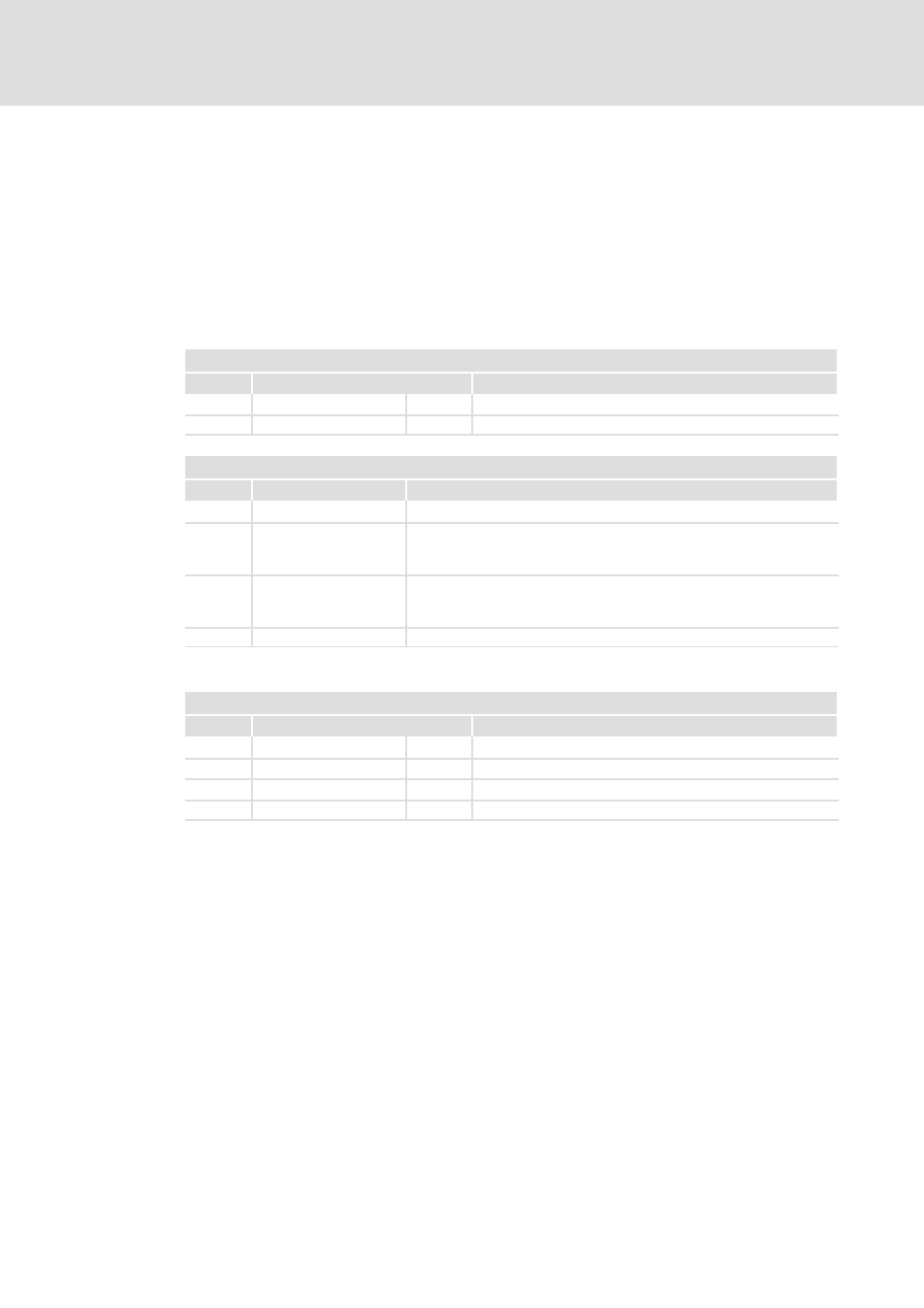
Read data: 4 bytes
Input area
Addr.
Name
Byte
Function
+0
PWMSTS_I
2
PWM 1: status
+2
PWMSTS_II
2
PWM 2: status
Status PVMx
Bit
Name
Function
0
−
Reserved
1
STS_PVM
Status PWM
0: PWM output stopped
1: PWM output active
2
STS_OUTBV
Output status
0: push/pull output
1: highside output
3 ... 15
−
Reserved
Write data: 12 bytes
Output area
Addr.
Name
Byte
Function
+0
PWMPD_I
4
PWM 1: pulse duration
+4
PWMSTS_II
4
PWM 2: pulse duration
+8
PWMCTRL_I
2
PWM 1: control word
+10
PWMSTS_II
2
PWM 2: control word
PWMPD_I, PWMPD_II pulse duration:Determine the scanning ratio for the parameterised
period here by stating the duration of the HIGH level for the corresponding PWM channel.
The pulse duration should be chosen as a factor for the 20.83 ns basis.
Value range: 48 ... 8388607 (1
ms ... approx. 175ms)
PWMPD_I, PWMPD_II control word:here you can specify the PWM output response for the
corresponding channel and start or stop PWM output.