3 multi-master system, Multi−master system, Profibus communication – Lenze I/O system 1000 System Manual User Manual
Page 388
PROFIBUS communication
System configuration
Multi−master system
l
388
EDSIO1000 EN 7.0
9.2.3
Multi−master system
Token
Master 1
(DPM 1)
Master 3
(DPM 1)
Master 2
(DPM 2)
Slave 1
Slave 2
Slave 3
Slave 4
Slave 5
Slave 6
0
1
2
epm−t226
Fig. 9−2
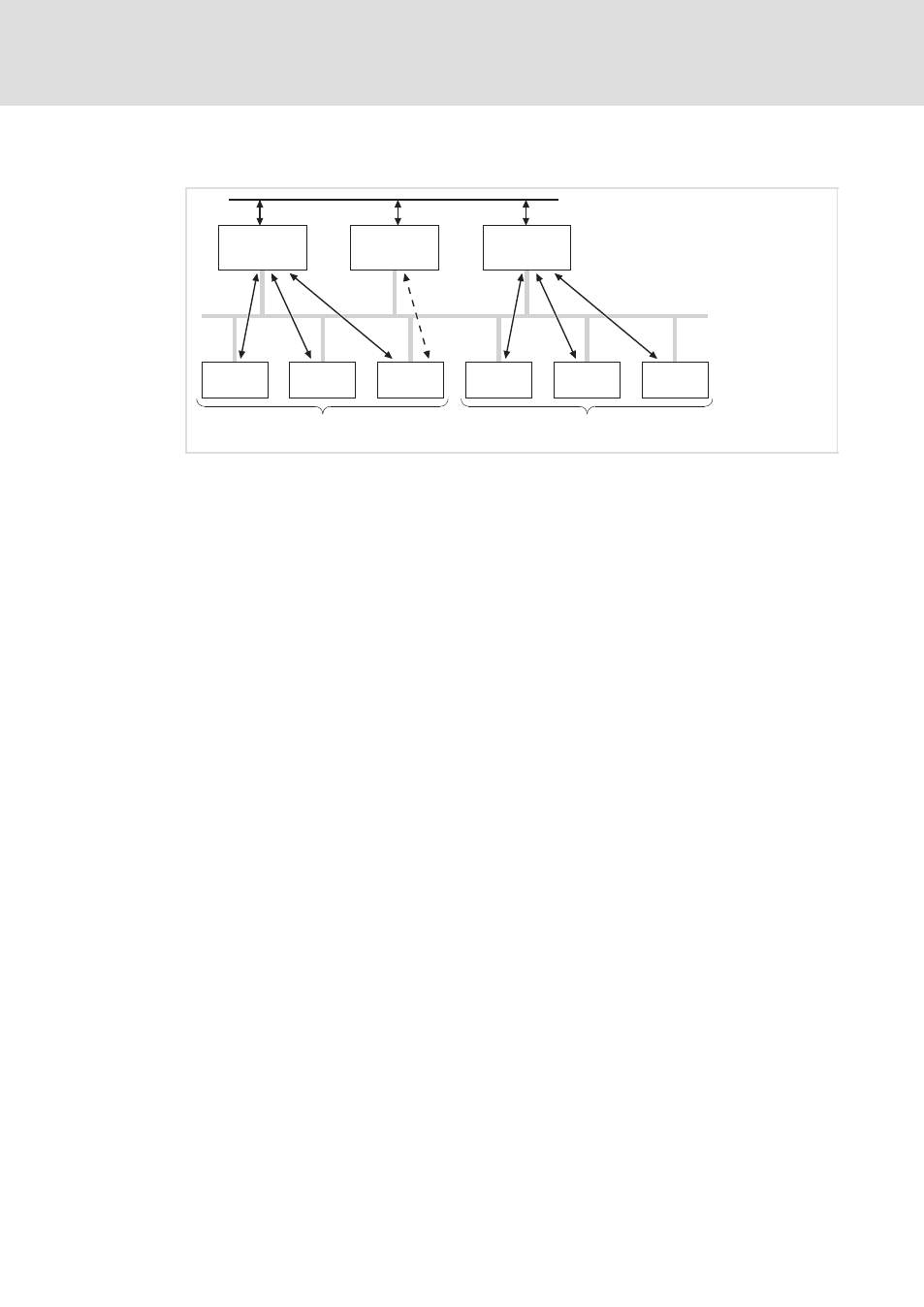
PROFIBUS−DP multi−master system
0
Subsystem consisting of master 1 and slaves 1 ... 3 with cyclic data transfer.
1
Subsystem consisting of master 3 and slaves 4 ... 6 with cyclic data transfer.
2
For configuration and diagnostics, master 2 can communicate with slave 1 ... 6. The data
transfer is acyclic.
In multi−master operation, several masters are connected to one bus. They either form
independent subsystems consisting of one class 1 master (DPM 1) each and the
corresponding slaves, or additional class 2 masters (DPM 2) for configuration and
diagnostics. The input and output images of the slaves can be read by all masters. Only the
respective class 1 master (DPM 1) can write the outputs.
- p300 Mounting Instructions (12 pages)
- p300 Operating Instructions (37 pages)
- CS5800 Mounting Instructions (89 pages)
- CS5800 Operating Instructions (60 pages)
- Controller-based Automation (63 pages)
- Controller-based Automation (68 pages)
- 2121IB LECOM-Li (29 pages)
- HMI for visualisation / with control technology (96 pages)
- Controller 3200 C Operating Instructions (40 pages)
- c300 Operating Instructions (35 pages)
- EL 1800 Mounting Instructions (89 pages)
- EL 1800 Operating Instructions (57 pages)
- 3200 C (38 pages)
- 3200 C (195 pages)
- CPC 2800 Mounting Instructions (59 pages)
- CPC 2800 Operating Instructions (39 pages)
- CS 5000 DVI Mounting Instructions (86 pages)
- CS 5000 DVI Operating Instructions (53 pages)
- MP 800 DVI Mounting Instructions (88 pages)
- MP 800 Operating Instructions (43 pages)
- 8400 protec Manual (198 pages)
- 8400 motec Manual (121 pages)
- 8400 motec Mounting Instructions (164 pages)
- 9400 Manual (584 pages)
- 9400 Mounting Instructions (208 pages)
- 8400 (304 pages)
- 8400 (1494 pages)
- i700 Manual (159 pages)
- 8400 BaseLine Manual (114 pages)
- 8400 BaseLine Guide Quick Guide (10 pages)
- EZAEDE1000 (76 pages)
- EMF2180IB EthernetCAN (134 pages)
- EMF2181IB (154 pages)
- EMF2181IB (83 pages)
- EMF2177IB (28 pages)
- EMF2177IB (18 pages)
- E84AZESR RFI filter 3-29A (154 pages)
- E84AZESM Mains filter-RFI filter 42-96A (120 pages)
- ESVZAR0 RS-485 (33 pages)
- ESV SMV frequency inverter (66 pages)
- CANopen Controller-based Automation (110 pages)
- PROFIBUS Controller-based Automation (55 pages)
- EtherCAT Controller-based Automation (205 pages)
- PROFINET Controller-based Automation (44 pages)