Product description – Lenze I/O system 1000 System Manual User Manual
Page 45
Product description
Bus coupler modules
EtherCAT − EPM−S130
l
45
EDSIO1000 EN 7.0
Overview
Re
c
e
ive
+
T
ransmit
-
Re
c
e
ive
-
T
ransmit
+
8
1
IN
OUT
2
6
3
7
4
8
1
5
DC 24 V
0 V
DC 24 V
0 V
DC 24 V
0 V
DC 24 V
0 V
F
2
3
0
1
4
5
4 5
/
2
6
6
7
SLIOS130/SLIOS700
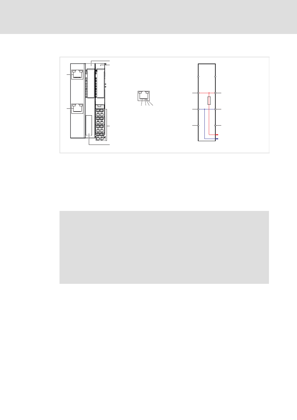
Fig. 3−11
Elements and circuit diagram of voltage supply
0
Displays for station and fieldbus status
1
Displays for electronics and I/O supply status
2
Terminals for the voltage supply
3
Bus interface
4
RJ45 socket OUT
5
RJ45 socket IN
6
Electronic supply
7
I/O supply
)
Note!
EtherCAT uses the Ethernet as its transmission medium. Only EtherCAT
components may be used in an EtherCAT network. To produce topologies
deviating from the line topology, you will need the corresponding EtherCAT
components which support such deviations. Hubs cannot be used.
An EtherCAT network always consists of a master and any number of EtherCAT
slaves (bus couplers). Each EtherCAT slave has an "IN" and "OUT" RJ45 socket.
The EtherCAT cable from the master should be plugged into the socket marked
as "IN". The socket marked as "OUT" should be connected to the following
node. The "OUT" socket on the last node is free.