Product description, System overview system design – Lenze I/O system 1000 System Manual User Manual
Page 24
Product description
System overview
System design
l
24
EDSIO1000 EN 7.0
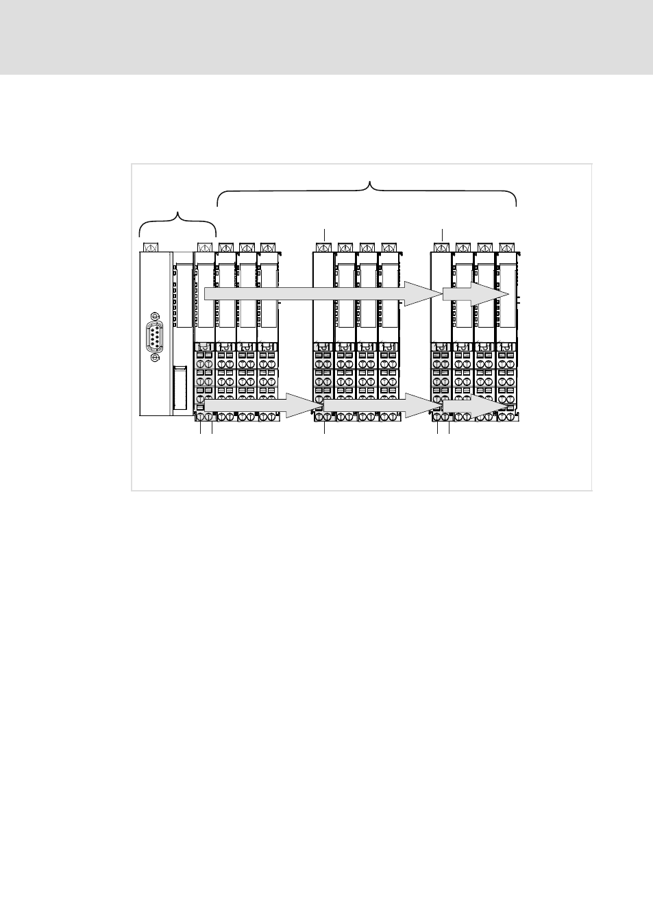
If, in the case of great station designs, the power of the main bus coupler supply does not
suffice to supply the I/O level and/or the electronics, power supply modules can be used.
Each supply provides an individual separate potential area.
Bus coupling
module
EPM-S1xx
up to 64 I/O compound modules EPM-S2xx ... EPM-S6xx
electronics supply DC 5 V / 3 A
I/O supply DC 24 V / 7 A *
)
I/O supply
*
)
DC 24 V / 7 A
Power supply module
I/O supply
EPM-S701
Power supply module
I/O supply and electronics supply
EPM-S702
DC 5 V / 2 A
DC 24 V / 4 A
...
...
DC
2
4
V
/
0
V
DC
2
4
V
/
0
V
DC
2
4
V
/
0
V
DC
2
4
V
/
0
V
DC
2
4
V
/
0
V
SLIO011
Fig. 3−2
Grouping through power supply modules
*)
If no UL conformity is required, the maximum permissible load for the I/O supply is 10 A.
For the supply of external consumers via the I/O system 1000 you can use power
distributor modules (EPM−S9xx) which provide the 24 V and/or 0 V voltage of the I/O
supply via their terminals.
- p300 Mounting Instructions (12 pages)
- p300 Operating Instructions (37 pages)
- CS5800 Mounting Instructions (89 pages)
- CS5800 Operating Instructions (60 pages)
- Controller-based Automation (63 pages)
- Controller-based Automation (68 pages)
- 2121IB LECOM-Li (29 pages)
- HMI for visualisation / with control technology (96 pages)
- Controller 3200 C Operating Instructions (40 pages)
- c300 Operating Instructions (35 pages)
- EL 1800 Mounting Instructions (89 pages)
- EL 1800 Operating Instructions (57 pages)
- 3200 C (38 pages)
- 3200 C (195 pages)
- CPC 2800 Mounting Instructions (59 pages)
- CPC 2800 Operating Instructions (39 pages)
- CS 5000 DVI Mounting Instructions (86 pages)
- CS 5000 DVI Operating Instructions (53 pages)
- MP 800 DVI Mounting Instructions (88 pages)
- MP 800 Operating Instructions (43 pages)
- 8400 protec Manual (198 pages)
- 8400 motec Manual (121 pages)
- 8400 motec Mounting Instructions (164 pages)
- 9400 Manual (584 pages)
- 9400 Mounting Instructions (208 pages)
- 8400 (304 pages)
- 8400 (1494 pages)
- i700 Manual (159 pages)
- 8400 BaseLine Manual (114 pages)
- 8400 BaseLine Guide Quick Guide (10 pages)
- EZAEDE1000 (76 pages)
- EMF2180IB EthernetCAN (134 pages)
- EMF2181IB (154 pages)
- EMF2181IB (83 pages)
- EMF2177IB (28 pages)
- EMF2177IB (18 pages)
- E84AZESR RFI filter 3-29A (154 pages)
- E84AZESM Mains filter-RFI filter 42-96A (120 pages)
- ESVZAR0 RS-485 (33 pages)
- ESV SMV frequency inverter (66 pages)
- CANopen Controller-based Automation (110 pages)
- PROFIBUS Controller-based Automation (55 pages)
- EtherCAT Controller-based Automation (205 pages)
- PROFINET Controller-based Automation (44 pages)