Product description – Lenze I/O system 1000 System Manual User Manual
Page 55
Product description
Bus coupler modules
DeviceNet − EPM−S150
l
55
EDSIO1000 EN 7.0
Overview
DR
CH
V+
CL
V-
1
5
2
6
3
7
4
8
1
5
DC 24 V
0 V
DC 24 V
0 V
DC 24 V
0 V
DC 24 V
0 V
F
4
2
3
0
1
4
2
5
5
6
SLIOS150/SLIOS700
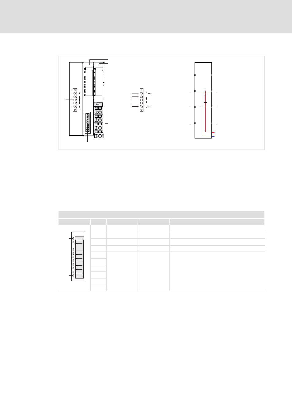
Fig. 3−13
Elements and circuit diagram of voltage supply
0
Displays for station and fieldbus status
1
Displays for electronics and I/O supply status
2
Terminals for the voltage supply
3
Coding switch for setting the DeviceNet address
4
Fieldbus connection
5
Electronic supply
6
I/O supply
Status displays
Fieldbus status LEDs
0
View
Pos.
Designation
Colour
Explanation
1
10
1
PW
Green
On: Bus coupler is supplied with voltage
2
SF
Red
On: Error at DeviceNet or at backplane bus
3
RD
Green
On: Backplane bus okay
4
BA
Yellow
On: DeviceNet okay
5
−
−
Not assigned
6
7
8
9
SLIO001
10
See also other documents in the category Lenze Equipment:
- p300 Mounting Instructions (12 pages)
- p300 Operating Instructions (37 pages)
- CS5800 Mounting Instructions (89 pages)
- CS5800 Operating Instructions (60 pages)
- Controller-based Automation (63 pages)
- Controller-based Automation (68 pages)
- 2121IB LECOM-Li (29 pages)
- HMI for visualisation / with control technology (96 pages)
- Controller 3200 C Operating Instructions (40 pages)
- c300 Operating Instructions (35 pages)
- EL 1800 Mounting Instructions (89 pages)
- EL 1800 Operating Instructions (57 pages)
- 3200 C (38 pages)
- 3200 C (195 pages)
- CPC 2800 Mounting Instructions (59 pages)
- CPC 2800 Operating Instructions (39 pages)
- CS 5000 DVI Mounting Instructions (86 pages)
- CS 5000 DVI Operating Instructions (53 pages)
- MP 800 DVI Mounting Instructions (88 pages)
- MP 800 Operating Instructions (43 pages)
- 8400 protec Manual (198 pages)
- 8400 motec Manual (121 pages)
- 8400 motec Mounting Instructions (164 pages)
- 9400 Manual (584 pages)
- 9400 Mounting Instructions (208 pages)
- 8400 (304 pages)
- 8400 (1494 pages)
- i700 Manual (159 pages)
- 8400 BaseLine Manual (114 pages)
- 8400 BaseLine Guide Quick Guide (10 pages)
- EZAEDE1000 (76 pages)
- EMF2180IB EthernetCAN (134 pages)
- EMF2181IB (154 pages)
- EMF2181IB (83 pages)
- EMF2177IB (28 pages)
- EMF2177IB (18 pages)
- E84AZESR RFI filter 3-29A (154 pages)
- E84AZESM Mains filter-RFI filter 42-96A (120 pages)
- ESVZAR0 RS-485 (33 pages)
- ESV SMV frequency inverter (66 pages)
- CANopen Controller-based Automation (110 pages)
- PROFIBUS Controller-based Automation (55 pages)
- EtherCAT Controller-based Automation (205 pages)
- PROFINET Controller-based Automation (44 pages)