Product description – Lenze I/O system 1000 System Manual User Manual
Page 153
Product description
I/O compound modules − temperature measurement
Two analog inputs for thermocouple measurement − EPM−S405
l
153
EDSIO1000 EN 7.0
Overview
DC24V
0V
AI
1
2
3
4
5
6
7
8
EPM-S405
AI1
AI2
1
0
SLIOS405
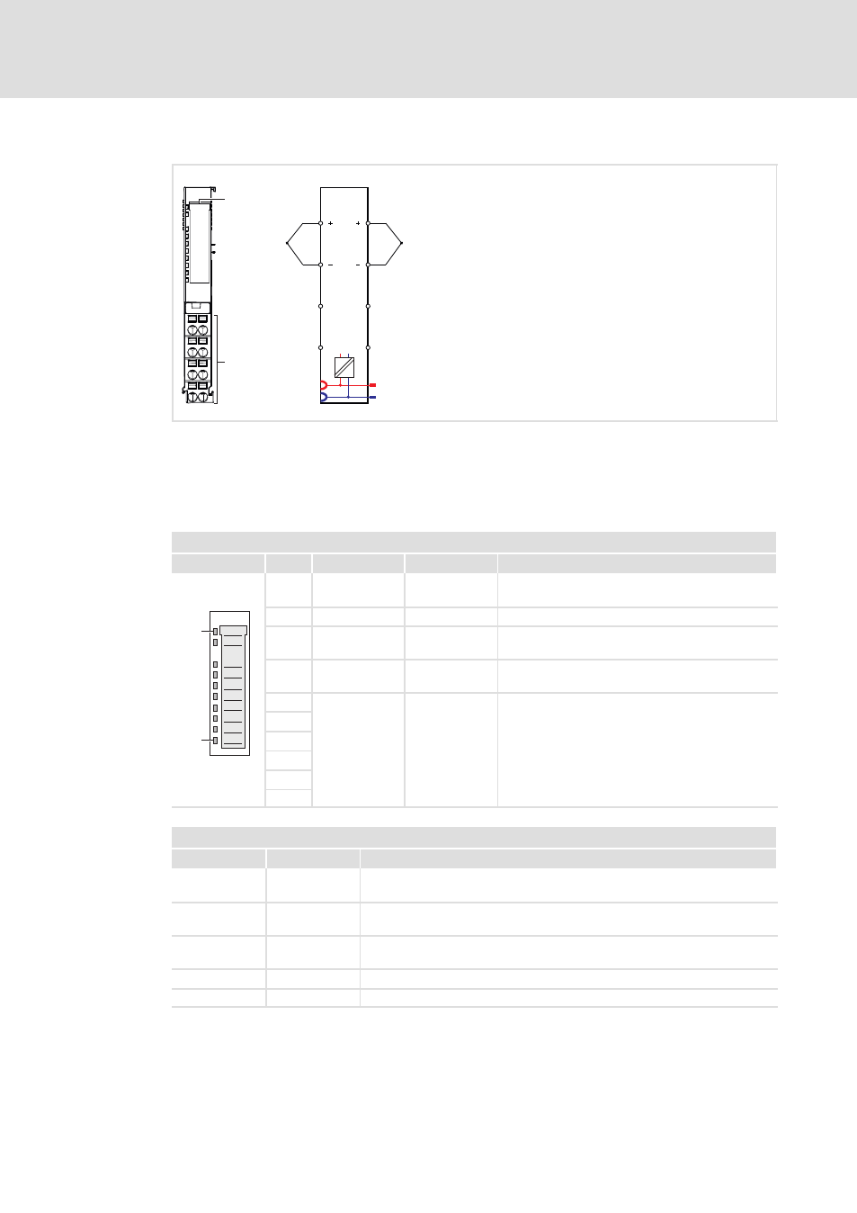
Fig. 3−40
Elements and circuit diagram
0
Displays for module status
1
Terminals
1 ... 8
Connection number
Status displays
Module status LEDs
0
View
Pos.
Designation
Colour
Explanation
1
10
1
RUN
Green
On: Module is ready for operation (see following
table)
2
MF
Red
On: Module error (see table below)
3
AI1
Red
On: Channel 1, signal outside the measuring range,
parameterisation error, open circuit
4
AI2
Red
On: Channel 2, signal outside the measuring range,
parameterisation error, open circuit
5
−
−
Not assigned
6
7
8
9
SLIO001
10
Messages of the status LEDs RUN and MF
RUN
MF
Meaning
On
Off
Module status OK
Bus communication is OK
On
On
Module reports error
Bus communication is OK
Off
On
Module reports error
Bus communication not possible
Off
Off
Error in the bus supply voltage
Blinking
Blinking
Configuration error (
^ 249)
- p300 Mounting Instructions (12 pages)
- p300 Operating Instructions (37 pages)
- CS5800 Mounting Instructions (89 pages)
- CS5800 Operating Instructions (60 pages)
- Controller-based Automation (63 pages)
- Controller-based Automation (68 pages)
- 2121IB LECOM-Li (29 pages)
- HMI for visualisation / with control technology (96 pages)
- Controller 3200 C Operating Instructions (40 pages)
- c300 Operating Instructions (35 pages)
- EL 1800 Mounting Instructions (89 pages)
- EL 1800 Operating Instructions (57 pages)
- 3200 C (38 pages)
- 3200 C (195 pages)
- CPC 2800 Mounting Instructions (59 pages)
- CPC 2800 Operating Instructions (39 pages)
- CS 5000 DVI Mounting Instructions (86 pages)
- CS 5000 DVI Operating Instructions (53 pages)
- MP 800 DVI Mounting Instructions (88 pages)
- MP 800 Operating Instructions (43 pages)
- 8400 protec Manual (198 pages)
- 8400 motec Manual (121 pages)
- 8400 motec Mounting Instructions (164 pages)
- 9400 Manual (584 pages)
- 9400 Mounting Instructions (208 pages)
- 8400 (304 pages)
- 8400 (1494 pages)
- i700 Manual (159 pages)
- 8400 BaseLine Manual (114 pages)
- 8400 BaseLine Guide Quick Guide (10 pages)
- EZAEDE1000 (76 pages)
- EMF2180IB EthernetCAN (134 pages)
- EMF2181IB (154 pages)
- EMF2181IB (83 pages)
- EMF2177IB (28 pages)
- EMF2177IB (18 pages)
- E84AZESR RFI filter 3-29A (154 pages)
- E84AZESM Mains filter-RFI filter 42-96A (120 pages)
- ESVZAR0 RS-485 (33 pages)
- ESV SMV frequency inverter (66 pages)
- CANopen Controller-based Automation (110 pages)
- PROFIBUS Controller-based Automation (55 pages)
- EtherCAT Controller-based Automation (205 pages)
- PROFINET Controller-based Automation (44 pages)