2 cyclic data transfer, Cyclic data transfer, Profibus communication – Lenze I/O system 1000 System Manual User Manual
Page 390
PROFIBUS communication
Communication
Cyclic data transfer
l
390
EDSIO1000 EN 7.0
9.3.2
Cyclic data transfer
The data communication with PROFIBUS−DP−V0 includes cyclic diagnostics as well as cyclic
process data and parameter data transfer.
Master
(DPM 1)
Slave
buffer receive
Communications
processor
PA
buffer send
PE
0
1
epm−t228
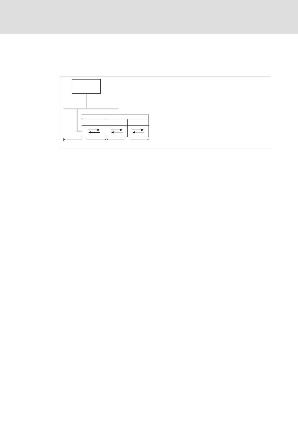
Fig. 9−3
DP cycle and cycle of backplane bus
0
Backplane bus with transmit and receive buffer
1
Input / output modules
PO: process image of outputs
PI: process image of inputs
PROFIBUS cycle
Backplane bus cycle
Backplane bus cycle
During a backplane bus cycle
ƒ
the input data (PI) on the inputs is collected and transmitted to the transmit buffer
(buffer send),
ƒ
the output data (PO) of the receive buffer (buffer receive) is written to the outputs.
PROFIBUS cycle
During a PROFIBUS cycle, the master successively addresses all its assigned slaves with a
DataExchange. During a DataExchange, the memory areas assigned to the PROFIBUS are
transmitted.
ƒ
The data of the PROFIBUS input area is transmitted to the receive buffer (buffer
receive).
ƒ
The data of the transmit buffer (buffer send) is transmitted to the PROFIBUS output
area.