Product description, Power supply modules i/o supply − epm−s701, Terminals – Lenze I/O system 1000 System Manual User Manual
Page 231
Product description
Power supply modules
I/O supply − EPM−S701
l
231
EDSIO1000 EN 7.0
Terminals
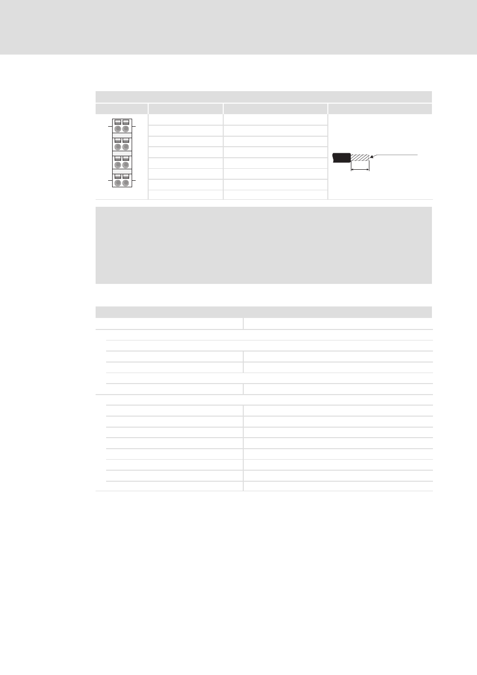
Module terminals, spring terminals
2
View
Designation
Explanation
Terminal data
2
6
3
7
4
8
1
5
1
5
4
8
1
Not assigned
10 mm
0.08 ... 1.5 mm²
(AWG 28 ... 16)
2
I/O supply +24 V DC
3
I/O supply 0 V
4
Not assigned
5
Not assigned
6
I/O supply +24 V DC
7
I/O supply 0 V
SLIO002
8
Not assigned
)
Note!
ƒ
Terminals 2 and 6 as well as 3 and 7 are bridged internally. Please note that
the max. permissible bridge current is 5 A.
ƒ
Both the I/O supply and the electronic supply are protected against overload
internally by a fuse. When the fuses have been tripped, the main supply of
the bus coupler (EPM−S700) must be replaced (
¶ 726).
Technical data
EPM−S701: Rated data
Module identifier
−
Electrical data
Input (supply)
Rated voltage
DC 24 V
Voltage range
DC 20.4 ... 28.8 V
Output
I/O supply
DC 24 V, max. 7 A (if UL conformity is required, max. 10 A)
Status, alarm, diagnostics
Status display
Yes
Alarms
No
Process alarm
No
Diagnostic alarm
No
Diagnostic function
No
Diagnostic information can be read out
No
Module status display
Green LED
Module error display
Red LED