2 supply voltage connection, Supply voltage connection, Electrical installation – Lenze I/O system 1000 System Manual User Manual
Page 246
Electrical installation
Supply voltage connection
l
246
EDSIO1000 EN 7.0
6.2
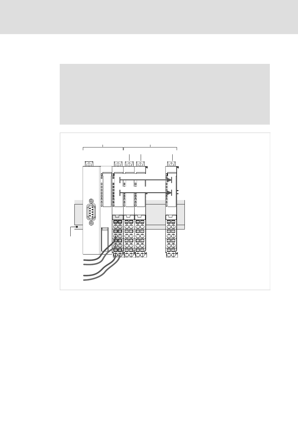
Supply voltage connection
)
Note!
The supply inputs of the bus coupler modules (main supply) and the power
supply modules are provided with internal fuses which protect them against
overvoltages.
The fuse is located in the main supply of the bus coupler module and in the
electronic module of the power supply module. If this fuse has tripped, the
main supply or the electronic module, respectively, needs to be replaced
(
¶ 726).
1
1
2
2
3
3
5
6
7
1
1
2
2
3
3
5
6
7
1
1
2
2
3
3
5
6
7
1
1
2
2
3
3
5
6
7
#n
DC 5 V / max. 3 A
...
#2
#1
DC 24 V
0 V
DC 24 V
0 V
0
0
0
0
DC 24 V
0 V
1
1
1
DC 24 V / max. 7 A
*)
0
+
I/O compound module
EPM-xxx
Bus coupling module
EPM-1xx
SLIO015
Fig. 6−1
Supply via bus coupler module (main supply)
*)
If no UL conformity is required, the maximum permissible load for the I/O supply is 10 A.
0 I/O supply
The I/O supply must be secured externally using a fuse that corresponds to the maximum
current: fast fuse, or circuit breaker with a Z characteristic
1 Electronic supply
We recommend securing the electronic supply externally according to the maximum current:
fast fuse, or circuit breaker with a Z characteristic