Brocade Mobility RFS Controller System Reference Guide (Supporting software release 5.5.0.0 and later) User Manual
Page 877
Brocade Mobility RFS Controller System Reference Guide
865
53-1003099-01
15
To view IPSec VPN status for tunnelled peers:
1. Select the Statistics menu from the Web UI.
2. Select a Wireless Controller node from the left navigation pane.
3. Select VPN and expand the menu to reveal its sub menu items.
4. Select IPSec.
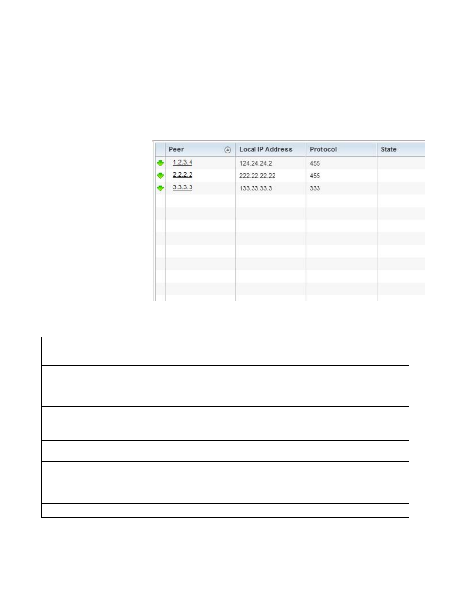
FIGURE 83
Wireless Controller - VPN IPSec screen
Review the following VPN peer security association statistics:
Peer
Lists IP addresses for peers sharing security associations (SA) for tunnel interoperability. When a peer
sees a sensitive packet, it creates a secure tunnel and sends the packet through the tunnel to its
destination.
Local IP Address
Displays each listed peer’s local tunnel end point IP address. This address represents an alternative to
an interface IP address.
Protocol
Lists the security protocol used with the VPN IPSec tunnel connection. SAs are unidirectional, existing in
each direction and established per security protocol. Options include ESP and AH.
State
Lists the state of each listed peer’s security association.
SPI In
Lists stateful packet inspection (SPI) status for incoming IPSec tunnel packets. SPI tracks each
connection traversing the IPSec VPN tunnel and ensures they are valid.
SPI Out
Lists SPI status for outgoing IPSec tunnel packets. SPI tracks each connection traversing the IPSec VPN
tunnel and ensures they are valid.
Mode
Displays the IKE mode as either Main or Aggressive. IPSEC has two modes in IKEv1 for key exchanges.
Aggressive mode requires 3 messages be exchanged between the IPSEC peers to setup the SA, Main
requires 6 messages
Clear All
Select the Clear All button to clear each peer of its current status and begin a new data collection.
Refresh
Select the Refresh
button to update the screen’s statistics counters to their latest values.