Allied Telesis AT-S62 User Manual
Page 448
Chapter 22: Multiple VLAN Modes
Section V: Virtual LANs
448
A user designated port on the switch functions as an uplink port, which
can be connected to a shared device, such as a router for access to a
WAN. This port is placed as a tagged port in each VLAN. Thus, while the
switch ports are separated from each other in their individual VLANs,
they all have access to the uplink port.
The uplink port also has its own VLAN, where it is an untagged member.
This VLAN is called Uplink_VLAN.
Note
In 802.1Q Multiple VLAN mode, the device connected to the uplink
port must be IEEE 802.1Q-compliant.
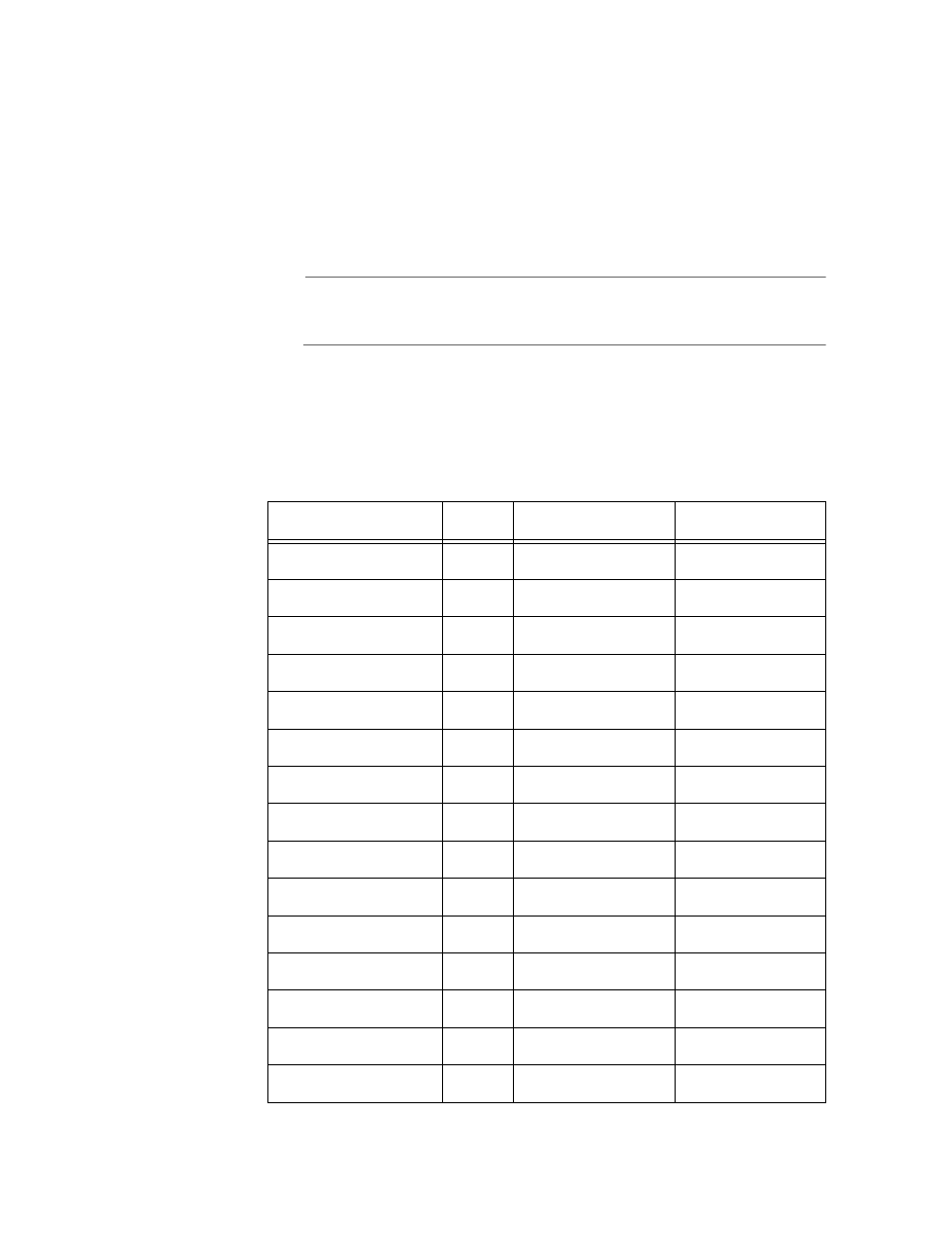
An example of the 802.1Q-compliant VLAN mode is shown in Table 24.
The table shows the VLANs on an AT-8524M switch where Port 25, a port
on an expansion module, has been selected as the uplink port.
Table 24 802.1Q-Compliant Multiple VLAN Example
VLAN Name
VID
Untagged Port
Tagged Port
Client_VLAN_1
1
1
25
Client_VLAN_2
2
2
25
Client_VLAN_3
3
3
25
Client_VLAN_4
4
4
25
Client_VLAN_5
5
5
25
Client_VLAN_6
6
6
25
Client_VLAN_7
7
7
25
Client_VLAN_8
8
8
25
Client_VLAN_9
9
9
25
Client_VLAN_10
10
10
25
Client_VLAN_11
11
11
25
Client_VLAN_12
12
12
25
Client_VLAN_13
13
13
25
Client_VLAN_14
14
14
25
Client_VLAN_15
15
15
25