Port trunking overview, Port trunking guidelines, Figure 33: port trunk example – Allied Telesis AT-S62 User Manual
Page 122
Chapter 8: Port Trunking
Section I: Basic Operations
122
Port Trunking Overview
A port trunk is an economical way for you to increase the bandwidth
between two Ethernet switches. A port trunk is a group of ports that
have been grouped together to function as one logical path. A port
trunk increases the bandwidth between switches and is useful in
situations where a single physical data link between switches is
insufficient to handle the traffic load.
A port trunk always sends packets from a particular source to a particular
destination over the same link within the trunk. A single link is
designated for flooding broadcasts and packets of unknown destination.
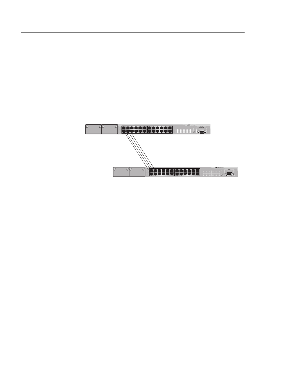
The example in Figure 33 consists of a port trunk of four data links
between two AT-8524M switches.
Figure 33 Port Trunk Example
Port Trunking
Guidelines
Observe the following guidelines when you create a port trunk:
❑ The switch can support up to six port trunks at a time.
❑ A port trunk can contain up to 8 ports.
❑ The ports of a port trunk must be of the same medium type. For
example, they can be all twisted pair ports or all fiber optic ports.
❑ The ports of a trunk can be either consecutive (for example Ports
5-9) or nonconsecutive (for example, Ports 4, 8, 11, 20).
❑ The speed, duplex mode, and flow control settings must be the
same for all the ports in a trunk.
❑ The ports of a port trunk must be untagged members of the same
VLAN. A port trunk cannot consist of untagged ports from
different VLANs.
LINK
MODE
LINK
MODE
FAULT
RPS
MASTER
PWR
MODE
STATUS
AT-8524M
Fast Ethernet Switch
LINK
MODE
LINK
MODE
FAULT
RPS
MASTER
PWR
MODE
STATUS
AT-8524M
Fast Ethernet Switch