Allied Telesis AT-S62 User Manual
Page 127
AT-S62 User’s Guide
Section I: Basic Operations
127
When another node sends a packet over the trunk, its address is
assigned to the next lowest port in the trunk, and so forth. After an
address has been assigned to all the ports in the trunk, the process is
repeated starting with the lowest numbered port.
Destination address trunking is typically used in a situation where there
is one or just a few source nodes transmitting to many destination
nodes. Switch #2 in Figure 34 on page 125 is an example of where this
type of load distribution would be useful. The server connected to the
switch is sending packets to multiple destination nodes.
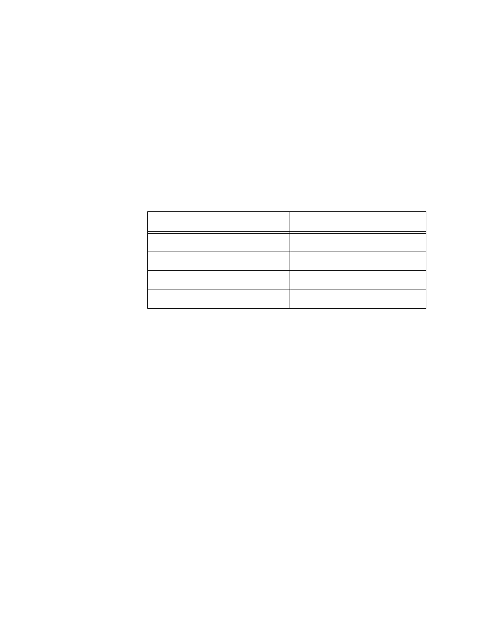
Table 2 shows how Switch #2 might distribute the server traffic across
the ports of the trunk using the destination MAC address method.
For example, when the server connected to Switch #2 needs to send a
packet to Workstation C, the switch uses port 13.
Source Address/Destination Address Distribution Methods
With this distribution method, a switch creates a matrix of the source
and destination addresses and then uses the matrix to determine which
port in the trunk a frame is to be transmitted. With this method, packets
from a particular source node might be sent over different data links in a
trunk when sent to different destination addresses.
As an example of how this works, assume that you configured Switch #2
in our example with source MAC address/destination MAC address. The
result might be something similar to that shown in Table 3.
Table 2 Switch #2 - Destination MAC Address Load Distribution
Method
Destination Address
Trunk Port
Workstation A - 00A0EE 2313A3
14
Workstation B - 00A134 1A9032
13
Workstation C - 00A301 9083B2
13
Workstation D - 001B21 87C6D6
15