Figure 115: spanning regions - example 1 – Allied Telesis AT-S62 User Manual
Page 367
AT-S62 User’s Guide
Section IV: Spanning Tree Protocols
367
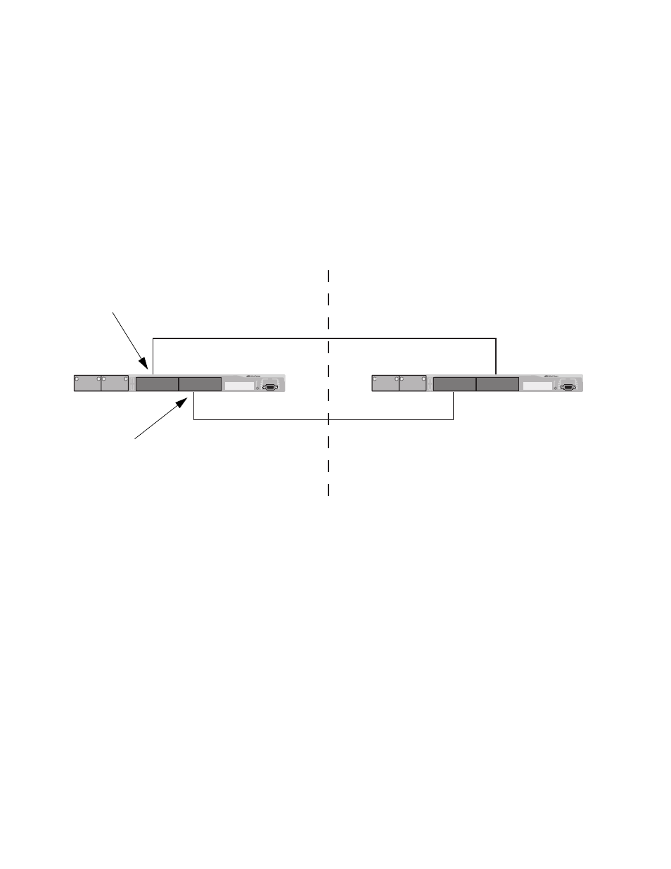
This is illustrated in Figure 115. The example show two switches, each
residing in a different region. Port 5 in Switch A is a boundary port. It is
an untagged member of the Accounting VLAN, which has been
associated with MSTI 4. Port 15 is a tagged and untagged member of
three different VLANs, all associated to MSTI 12.
If both switches were a part of the same region, there would be no
problem since the ports reside in different spanning tree instances.
However, the switches are part of different regions and MSTIs do not
cross regions. Consequently, the result would be that spanning tree
would determine that a loop exists between the regions, and Switch B
would block a port.
Figure 115 Spanning Regions - Example 1
There are several ways to address this issue. One is to have only one
MSTP region for each subnet in your network.
Another approach is to group those VLANs that need to span regions
into the same MSTI. Those VLANs that do not span regions can be
assigned to other MSTIs.
AT-8524M
AT-8524M
Region 1
Region 2
Switch A
Switch B
Port 15
VLAN (untagged port): Sales
MSTI 12
VLAN (tagged port): Presales
VLAN (tagged port): Marketing
Port 5
MSTI 4
VLAN (untagged) port: Accounting