Figure 134: gvrp example – Allied Telesis AT-S62 User Manual
Page 422
Chapter 21: GARP VLAN Registration Protocol
Section V: Virtual LANs
422
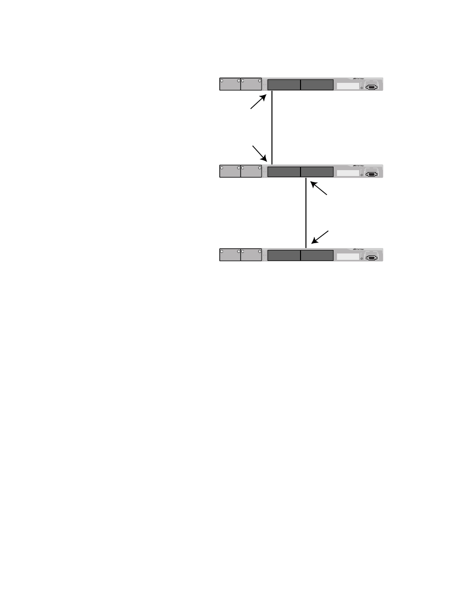
Figure 134 provides an example of how GVRP works.
Figure 134 GVRP Example
Switches #1 and #3 contain the Sales VLAN, but Switch #2 does not.
Consequently, the end nodes of the two parts of the Sales VLANs are
unable to communicate with each other.
Without GVRP, you would need to configure Switch #2 by creating the
Sales VLAN on the switch and adding ports 4 and 15 on the switch as
members of the VLAN. If you happen to have a large network with a
large number of VLANs, such manual configurations can be
cumbersome and time consuming.
GVRP can make the configurations for you. Here is how GVRP would
resolve the problem in the example.
1. Port 1 on Switch #1 sends a PDU to Port 4 on Switch #2, containing the
VIDs of all the VLANs on the switch. One of the VIDs in the PDU would
be that of the Sales VLAN, VID 11.
2. Switch #2 examines the PDU it receives on Port 4 and notes that it
does not have a VLAN with a VID 11. So it creates the VLAN as a
dynamic GVRP VLAN and assigns it a VID 11 and the name
GVRP_VLAN_11. (The name of a dynamic GVRP VLAN has the prefix
“GVRP_VLAN_”, followed by the VID number.) The switch then adds
Port 4, the port that received the PDU, as a tagged member of the
VLAN.
Switch #1
Static VLAN
Sales VID=11
Port 1
Port 4
Switch #2
Switch #3
Static VLAN
Sales VID=11
AT-8524M
AT-8524M
AT-8524M
Port 15
Port 17