Figure 113: cist and vlan guideline - example 1 – Allied Telesis AT-S62 User Manual
Page 365
AT-S62 User’s Guide
Section IV: Spanning Tree Protocols
365
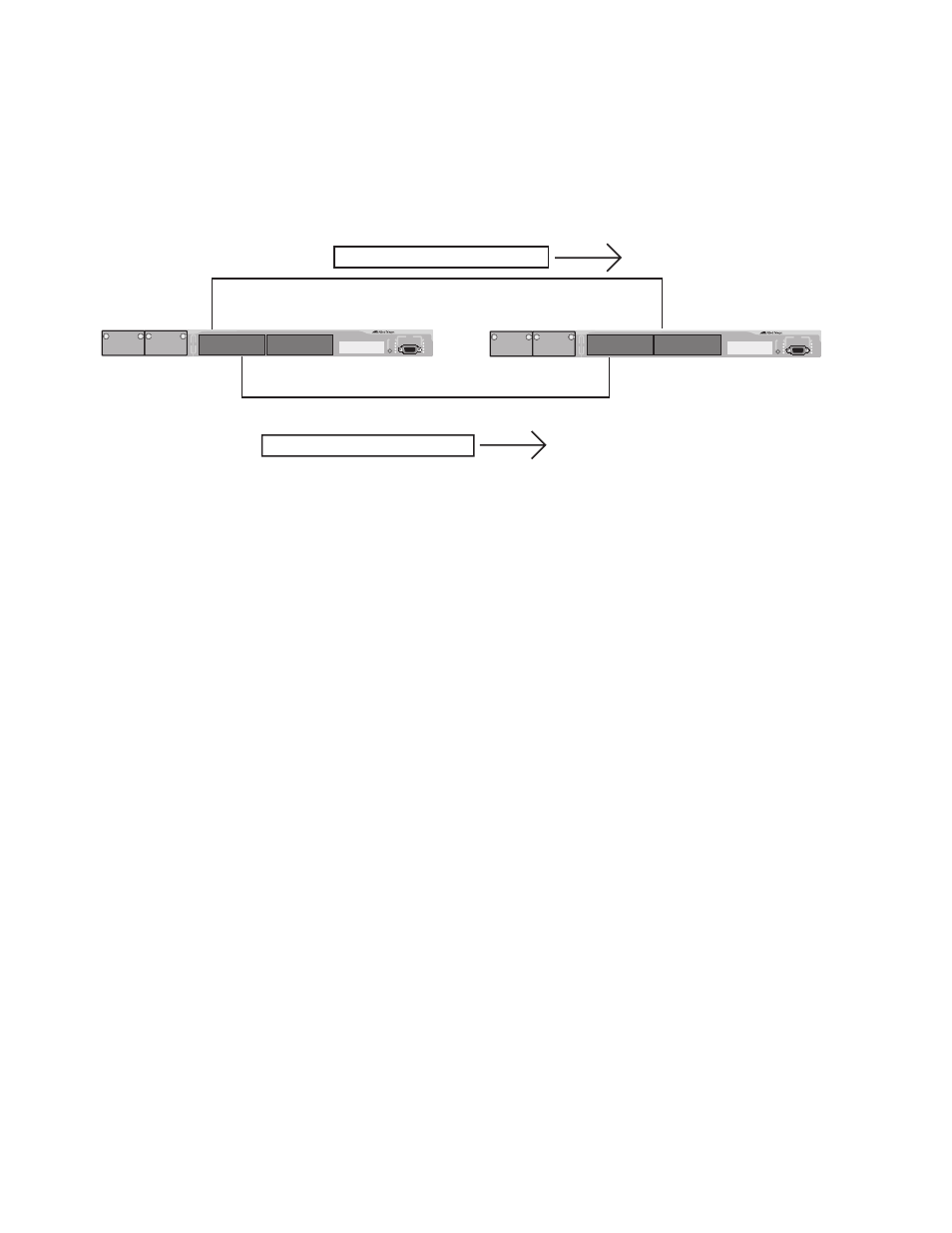
This is illustrated in Figure 113. Port 8 in Switch A is a member of a VLAN
assigned to MSTI ID 7 while Port 1 is a member of a VLAN assigned to
MSTI ID 10. The BPDUs transmitted by port 8 to Switch B would indicate
that the port is a member of both CIST and MSTI 7, while the BPDUs from
Port 1 would indicate the port is a member of the CIST and MSTI 10.
Figure 113 CIST and VLAN Guideline - Example 1
At first glance, it might appear that since both ports belong to CIST, a
loop would exist between the switches and that MSTP would block a
port to stop the loop. However, within a region, MSTI takes precedence
over CIST. When Switch B receives a packet from Switch A, it uses MSTI,
not CIST, to determine whether a loop exists. And since both ports on
Switch A belong to different MSTIs, Switch B determines that no loop
exists.
Instance: CIST 0 and MSTI 10
Instances: CIST 0 and MSTI 7
Port 8
Switch A
Switch B
BPDU Packet
Port 1
BPDU Packet
AT-8524M
AT-8524M