Figure 114: cist and vlan guideline - example 2 – Allied Telesis AT-S62 User Manual
Page 366
Chapter 19: Multiple Spanning Tree Protocol
Section IV: Spanning Tree Protocols
366
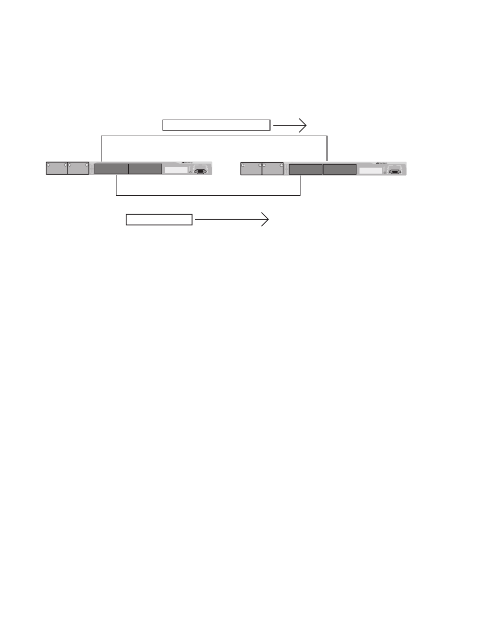
A problem can arise if you assign some VLANs to MSTIs while leaving
others just to CIST. The problem is illustrated in Figure 114. The network
is the same as the previous example. The only difference is that the VLAN
containing Port 8 on Switch A has not been assigned to an MSTI, and
belongs only to CIST with its MSTI ID 0.
Figure 114 CIST and VLAN Guideline - Example 2
When port 3 on Switch B receives a BPDU, the switch notes the port
sending the packet belongs only to CIST. Consequently, Switch B uses
CIST in determining whether a loop exists. The result would be that the
switch would determine that a loop exists because the other port is also
receiving BPDU packets from CIST 0. Switch B would block a port to
cancel the loop.
To avoid this issue, always assign all VLANs on a switch, including the
Default_VLAN, to an MSTI. This guarantees that all ports on the switch
have an MSTI ID and that helps to ensure that loop detection is based on
MSTI, not CIST.
Connecting VLANs Across Different Regions
Special consideration needs to be taken into account when connecting
different MSTP regions or an MSTP region and a single-instance STP or
RSTP region. Unless planned properly, VLAN fragmentation can occur
between the VLANS of your network.
As mentioned previously, only the CIST can span regions. A MSTI cannot.
Consequently, you may run into a problem if you use more than one
physical data link to connect together various parts of VLANs that reside
in bridges in different regions. The result can be a physical loop, which
spanning tree disables by blocking ports.
Instance: CIST 0 and MSTI 10
Instances: CIST 0
Port 8
Switch A
Switch B
BPDU Packet
Port 1
BPDU Packet
AT-8524M
AT-8524M
Port 3
Port 15