Grass Valley VM 3000 System Controllers v.7.4 User Manual
Page 82
Hardware Installation
2−10
VM 3000 Installation and Operating Manual
1
1
8
P1
DB15P
(male)
Shield (drain)
P2
DB15P
(male)
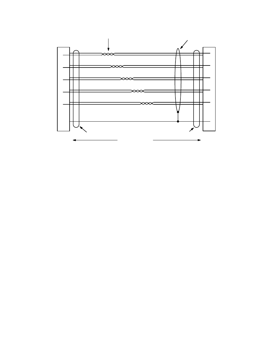
Figure 2−9. CC 2010 wiring. Reference: “Assembly, XPT Bus Cable Shield,” Grass Valley drawing no. 01−048592−TAB.
Red
9
Black
2
Yellow
10
Black
3
Green
11
Black
4
Blue
12
Black
5
White
13
Black
8
2
3
4
5
9
10
11
12
13
Twisted pairs
100 ft ( m) max
Shielded connector
Shielded connector
Shield
Red
Black
Yellow
Black
Green
Black
Blue
Black
White
Black
Reset
Data
Clock
Take
Confirm
Ground
This manual is related to the following products:
See also other documents in the category Grass Valley Equipment:
- LDK 5302 (24 pages)
- SFP Optical Converters (18 pages)
- 2000GEN (22 pages)
- 2011RDA (28 pages)
- 2010RDA-16 (28 pages)
- 2000NET v3.2.2 (72 pages)
- 2000NET v3.1 (68 pages)
- 2020DAC D-To-A (30 pages)
- 2000NET v4.0.0 (92 pages)
- 2020ADC A-To-D (32 pages)
- 2030RDA (36 pages)
- 2031RDA-SM (38 pages)
- 2041EDA (20 pages)
- 2040RDA (24 pages)
- 2041RDA (24 pages)
- 2042EDA (26 pages)
- 2090MDC (30 pages)
- 2040RDA-FR (52 pages)
- LDK 4021 (22 pages)
- 3DX-3901 (38 pages)
- LDK 4420 (82 pages)
- LDK 5307 (40 pages)
- Maestro Master Control Installation v.1.5.1 (455 pages)
- Maestro Master Control Installation v.1.5.1 (428 pages)
- 7600REF Installation (16 pages)
- 7600REF (84 pages)
- 8900FSS (18 pages)
- 8900GEN-SM (50 pages)
- 8900NET v.4.3.0 (108 pages)
- Safety Summary (17 pages)
- 8900NET v.4.0.0 (94 pages)
- 8906 (34 pages)
- 8911 (16 pages)
- 8900NET v.3.2.2 (78 pages)
- 8914 (18 pages)
- 8912RDA-D (20 pages)
- 8916 (26 pages)
- 8910ADA-SR (58 pages)
- 8920ADC v.2.0 (28 pages)
- 8920ADC v.2.0.1A (40 pages)
- 8920DAC (28 pages)
- 8920DMX (30 pages)
- 8920ADT (36 pages)
- 8920MUX (50 pages)
- 8921ADT (58 pages)