Appendix h, Venus three-stage switching, Venus three−stage switching – Grass Valley VM 3000 System Controllers v.7.4 User Manual
Page 677: Three−stage switchers, see appendix h, Switching, see appendix h.)
H−1
VM 3000 Installation and Operating Manual
Appendix H
Venus Three−stage Switching
Three−stage
§
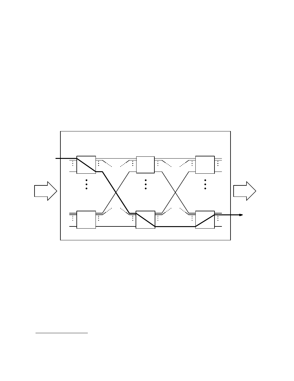
architecture is used for very large switchers as a means of reducing crosspoints needed for a given number of
inputs/outputs. An array of relatively small matrixes is arranged in an input stage, an intermediate stage, and an output stage.
The path taken by a required signal through these stages is determined by software and will vary according to which circuits
are already in use. An example of one level of a 512 x 512 switcher in shown in Figure H−1. The dark line shows a possible
signal path.
Input stage
32 16 x 32 matrixes
Output stage
32 32 x 16 matrixes
Intermediate stage
32 32 x 32 matrixes
512
In
512
Out
Figure H−1. One level of three−stage switcher (example)
Note: Three−stage switching is not the same as “path finding.” A three−stage switcher operates as one unit and
is carefully designed so that all inputs are always available at all outputs; i.e., it cannot be blocked. Path finding,
on the other hand, involves discrete switchers connected by a small number of tie lines, the number of which strictly
limits the inputs available at the downstream switcher. When these tie lines are all busy, the path between the
switchers is blocked and will remain so until one of the lines is released. (For more information about path−finding,
see page 5−194.)
§