Computers using rpx (rp−0000) protocol – Grass Valley VM 3000 System Controllers v.7.4 User Manual
Page 339
Configurator
MPK Devices
5−129
VM 3000 Installation and Operating Manual
COMPUTERS USING RPX (RP−0000) PROTOCOL
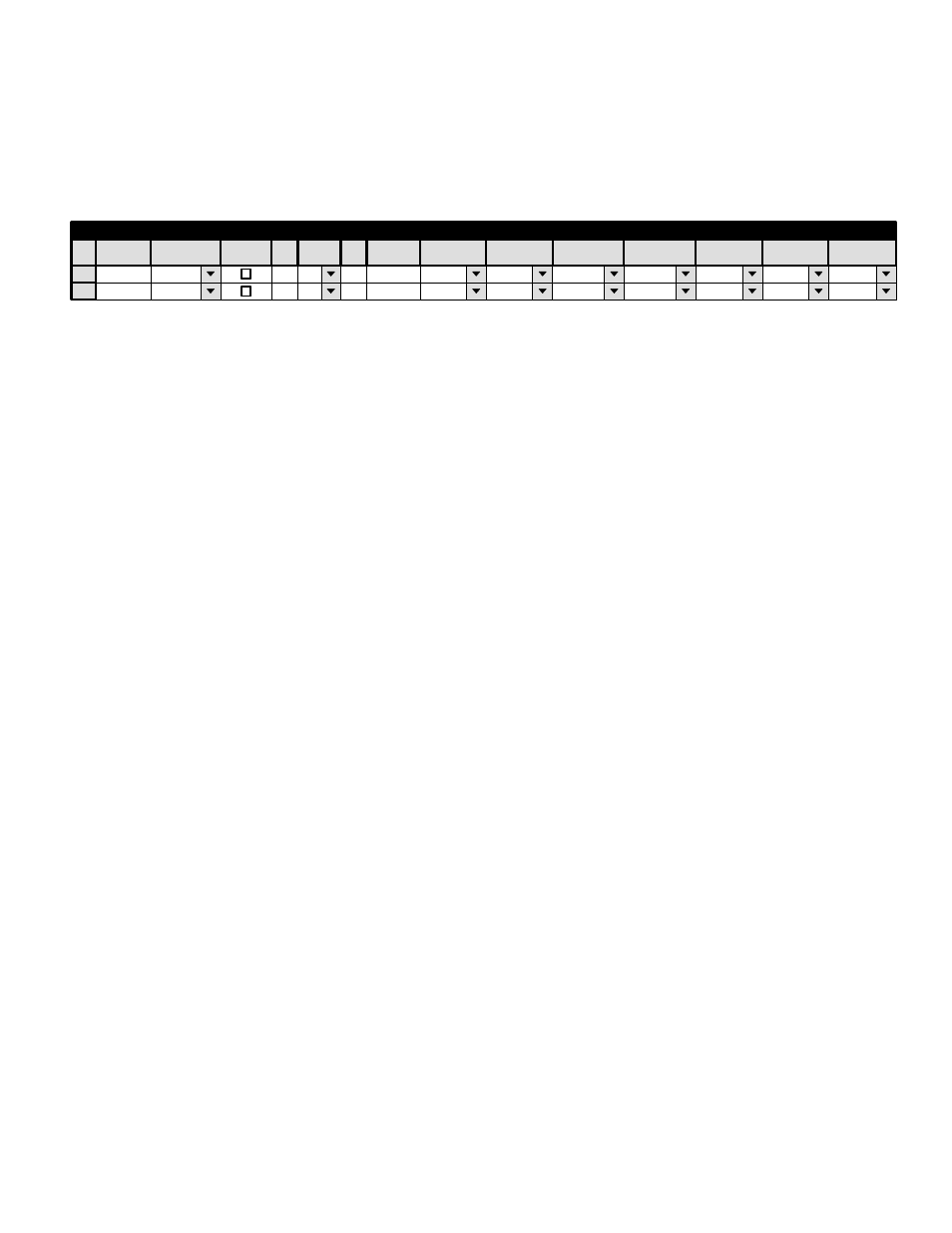
Hardware installation was discussed on page 2−86; serial port configuration was discussed on page 5−25. Figure 5−104 shows
an example table for the system shown on page 2−86.
SWITCHPC
Serial
SI3
8
PC−INP
PC−OUT
1
MPK Devices
MPK
Expansion
Pass
Board
Port
Address
Input Sets
Output Sets
Level Set
Overide Set
Sequence Set
2
KXYZ−LEV
Devices
word
In Panel
Out Panel
00000001
Device
Type
Figure 5−104. Entry for system shown on page 2−86.
For Device Type, select “Serial.”
The Address field contains the “site number” of the controlling computer. The site number, which is defined by the end−user,
must be a number from 0x01 to 0x7F hex (1−127 decimal). For example, if the site number is 16 decimal then “00000010”
must be entered into this field; if the site number is 15 decimal then “0000000F” must be entered into this field (see Appendix
D for a decimal−to−hexadecimal chart).
The Input, Output, and Level sets named on this table should include all inputs, outputs, and levels that will be controlled
by the external control computer. As a precaution, you may wish to restrict computer control to selected outputs.
The Input (page 5−58) and Output (page 5−76) sets must be created specifically for use by “serial” devices.
A technical description of the RPX computer interface protocol is available on request.