The system shown in figure l−14. the – Grass Valley VM 3000 System Controllers v.7.4 User Manual
Page 721
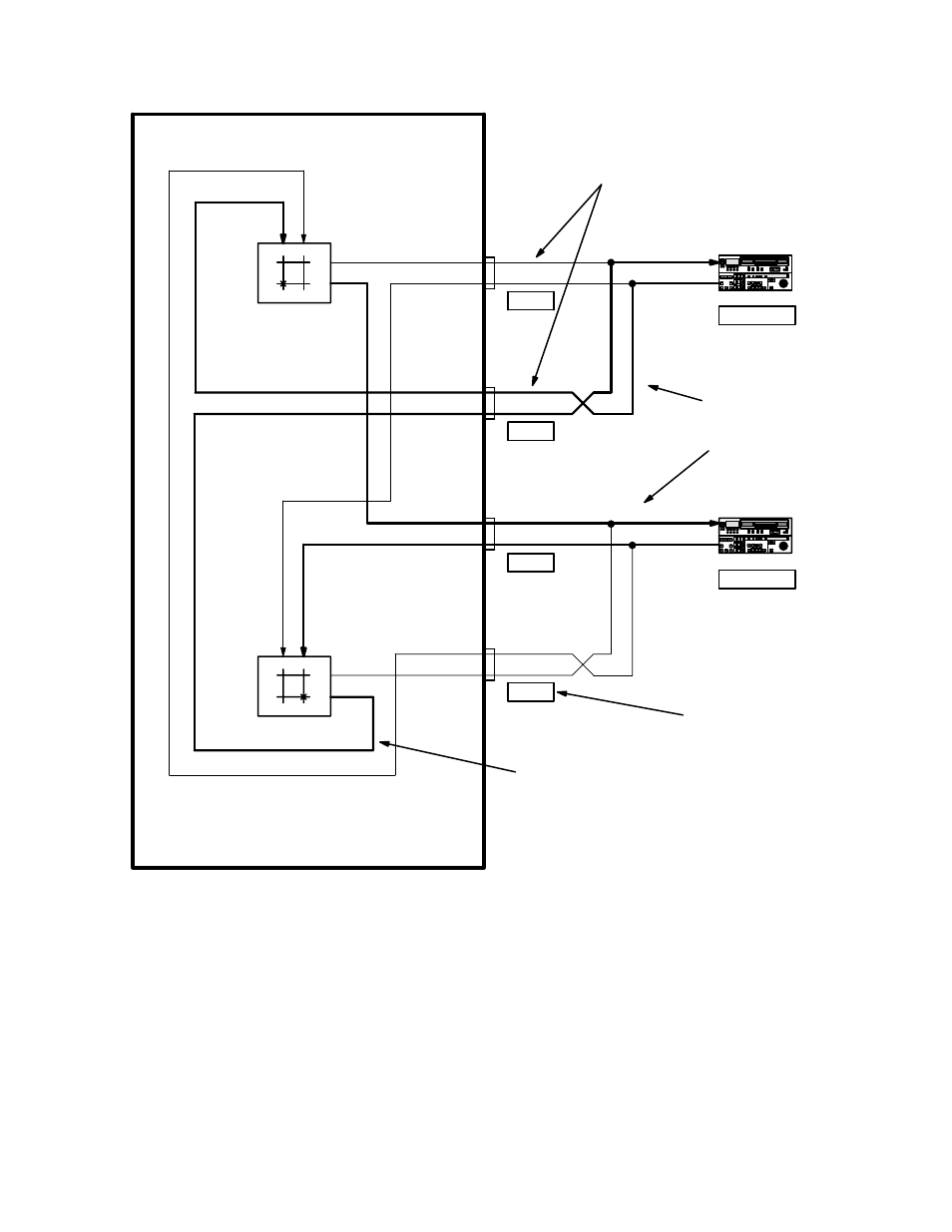
Venus DM 400/400A
L−9
VM 3000 Installation and Operating Manual
Rx
Tx
VR1
being used as Master
VR2
being used as Slave
Rx
Tx
Figure L−14. Example of Sony Master/Slave VTR ap-
plication showing forward and reverse switcher levels.
“VR1−S”
Port 1
Port 2
Venus Data Matrix
Port 3
For pin−outs of these
Controller
Tributary
Darker lines indicate
active signal paths
when VR 1 is
controlling VR 2.
Forward data
switcher level
“FOR”
Reverse data
switcher level
“REV”
Port 0
“VR1−M”
“VR2−S”
“VR2−M”
“VR1−S” is suggested as the name for VR 1
when used as a Slave. “VR1−M” is suggested
as the name for VR 1 when used as a Master.
“D−1”
“C−1”
“D−2”
“C−2”
Suggested
Category/Number for
control panel use.
This manual is related to the following products: