Vm 3000 switch settings, Rack mounting, Front – Grass Valley VM 3000 System Controllers v.7.4 User Manual
Page 74
Hardware Installation
2−2
VM 3000 Installation and Operating Manual
VM 3000 Switch Settings
Front
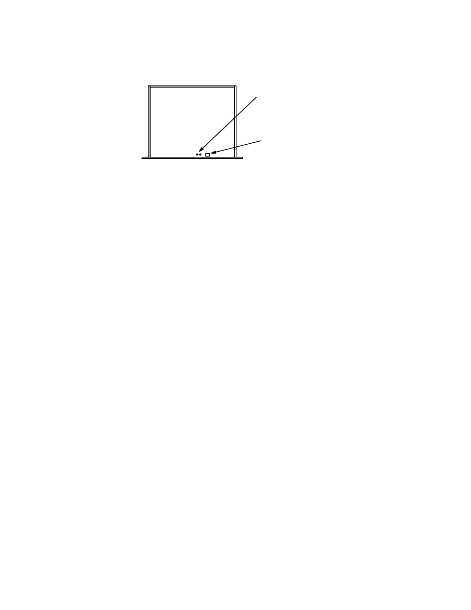
Figure 2−2. VM/SI 3000
rotary and DIP switch
locations.
Switch S1 is for factory test
purposes only. Default
settings are as follows:
S1−5 (watchdog enable) ON
All other switches OFF
S1 DIP switch
S3 and S2
rotary switches
Rotary switches S3 and S2 are
used to set the device address
Rack Mounting
Grass Valley recommends that each control chassis be near most of the devices which it will control, thus reducing system
cabling. The VM 3000 Control Processor should be located near the distribution switcher. Leaving ventilation space between
the rack mount units is not necessary.
System diagrams are shown in the following pages.
This manual is related to the following products: