Switcher description table – Grass Valley VM 3000 System Controllers v.7.4 User Manual
Page 715
Venus DM 400/400A
L−3
VM 3000 Installation and Operating Manual
SWITCHER DESCRIPTION TABLE
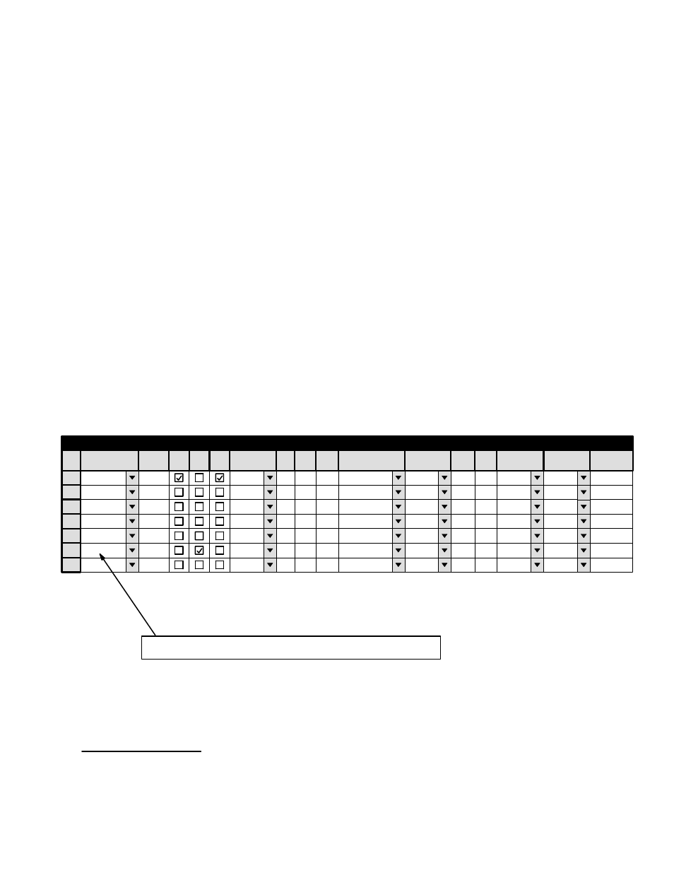
An example of a Switcher Description table for a DM 400/400A data matrix switcher is shown in Figure L−3. This table corre-
sponds to the system shown in Figures L−1 and L−2.
In this example, a special entry in the “Switcher” column (“DATA”) is used for the data router levels; this forces the Jupiter
software to create Switcher Input and Switcher Output tables that are separate from those used for other switcher levels (Fig-
ure L−6).
Note 1: A limitation in the present software requires that the entries in the “Switcher” column for the data router
levels must be the same as, or come alphabetically before, all other names used in the Switcher column. In Figure
L−3, this rule is satisfied because the letter “D” in “DATA” comes alphabetically before the letter “M” in “MAIN-
ROUT,” and before the letter “O” in “OLDROUT.” This does not mean that the entries must be in alphabetical
order within the table itself.
For DM 400/400A applications, the forward and reverse levels have the same physical level number (“16”). Reverse switch-
ing is enabled for the reverse level (“R”); and, the reverse level is made to follow the forward level (“DATA” and “FOR”).
The “Option” entry (normally “E”) is described starting on page 5−41.
Note 2: For DM 400/400A data switchers, the entry for “#In” must be “193.” This is true regardless of the actual
size of the switcher.
†
The Switcher Description table is described in more detail starting on page 5−31.
Figure L−3.
Name chosen for data router must sort alphabetically before names used
for other switchers (e.g., “D” comes in the alphabet before “M” and “O.”
1
Switcher Description
MAINROUT
M1
64
64
1
Binary
None
2
MAINROUT
M1
64
64
2
Binary
Left
3
MAINROUT
M1
64
64
8
Binary
Right
4
MAINROUT
M1
32
32
4
Binary
None
VIDEO
LEFT
RIGHT
TC
Switcher
VI
RV
Board
#In #Out PLvL
Follow Level
Driver
3 LI
3 LO
Option
Audio
Level
DM 400
MC
Off Time
5
DATA
M1
193 32
16
Binary
E
FOR
6
DATA
M1
193 32
16
FOR (DATA)
Binary
E
REV
7
OLDROUT
M1
10
10
3
TVS Prot
VIDEO
†
This is because the “#In” must always be one greater than the largest number used in the CP Input table. The largest number
used in the CP Input table will always be “192” (for the “safe” input, as described on page 5−25).