Example of saturn tally system – Grass Valley VM 3000 System Controllers v.7.4 User Manual
Page 187
Hardware Installation
2−115
VM 3000 Installation and Operating Manual
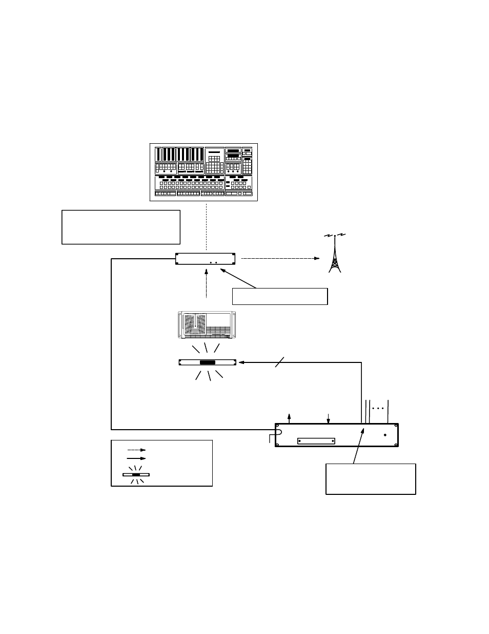
EXAMPLE OF SATURN TALLY SYSTEM
The following diagram shows an example of a Saturn Tally system. For detailed information, refer to “Saturn Tally” in the
Saturn Installation and Operating Manual.
Figure 2−129. Saturn Tally system.
MPK bus
MI 3040
General Purpose/
Tally Interface
+5 V utility
connection
Ground utility
connection
Video and audio
Control lines
Tally light
One connection per tally light.
100 V, 300 mA max.
Sources
ÎÎ
ÎÎ
ÎÎ
Î
Î
Î
Î
Î
Î
ÎÎ
ÎÎ
ÎÎ
ÎÎ
Î
Î
Î
Î
Î
Î
Î
Î
Î
Î
Î
ÎÎ
Î
Î
Î
Î
Î
Î
ÎÎ
ÎÎ
Î
Î
ÎÎ
Î
Î
Î
ÎÎ
ÎÎ
Î
ÎÎ
Î
Î
Î
Î
Î
Î
ÎÎ
ÎÎ
Î
Î
ÎÎ
Î
Î
Î
ÎÎ
ÎÎ
Î
ÎÎ
Î
Î
Î
Î
Î
Î
Î
Î
Î
Î
Î
Î
ÎÎ
ÎÎ
Î
Î
Î
Î
Î
Î
ÎÎ
Î
Î
Î
ÎÎ
Î
Î
Î
ÎÎ
Î
Î
Î
Î
Î
Î
Î
Î
ÎÎ
ÎÎ
ÎÎ
ÎÎ
ÎÎ
Î
ÎÎ
Î
Î
ÎÎ
Î
Î
Î
Î
Î
ÎÎ
ÎÎ
Î
Î
Î
Î
Î
Î
ÎÎ
Î
Î
Î
Î
ÎÎÎ
Î
ÎÎ
Î
Î
ÎÎ
Î
Î
Î
Î
ÎÎ
Î
Î
Î
ÎÎ
ÎÎÎ
ÎÎ
ÎÎ
Î
Î
Î
ÎÎ
Î
Î
Î
Î
ÎÎ
ÎÎ
Î
Î
Î
Î
Î
ÎÎ
ÎÎ
ÎÎ
ÎÎ
Î
ÎÎ
Î
Î
Î
Î
Î
Î
Î
Î
Î
Î
Î
Î
Î
Î
Î
ÎÎ
ÎÎ
ÎÎ
ÎÎ
ÎÎ
ÎÎ
Î
Î
Transmitter
Serial data cable (see page 2−109)
AVP 3500 or DVP 3500
video processor
All sources must be connected
directly to internal matrix.
When used as a connection point
for an MPK bus, the Saturn video
processor must be entered on the
Serial Protocol table (page 5−25).
40 relays. Wiring order is de-
termined automatically. See
Saturn Installation and Oper-
ating manual.