Cp 310 24 x 8 eight bus control panel, Etc.) – Grass Valley VM 3000 System Controllers v.7.4 User Manual
Page 124
Hardware Installation
2−52
VM 3000 Installation and Operating Manual
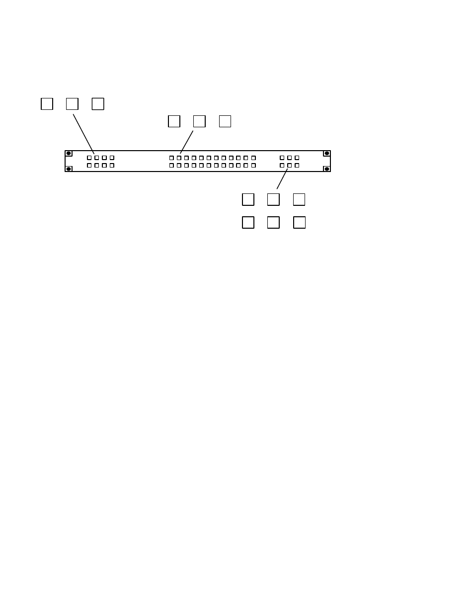
CP 310 24 X 8 Eight Bus Control Panel
Installation is shown on page 2−50.
Figure 2−60. CP 310 Control Panel (as supplied).
0
1
2
(etc.)
0
1
2
(etc.)
CHG
VID
CHG
A1
CHG
A2
CHG
A3
CHG
A4
CHG
A5
The CP 310 Control Panel is very similar to the CP 300 Control Panel, except that eight buttons on the left side of the panel
are used to control eight outputs. Refer to the CP 300 discussion (page 2−51) for installation instructions.
The buses to be controlled are listed in an “Output Set” (page 5−76); the name of the Output Set is entered on the MPK Devices
table (page 5−109).
This manual is related to the following products: