Lock output, To lock an output, To unlock an output – Grass Valley VM 3000 System Controllers v.7.4 User Manual
Page 431: Vtr1 vt1l vt1r vt1t lock − press take, Ab c d, F4 f3 f2 f1

Control Panel Operation
CP 3000
6−11
VM 3000 Installation and Operating Manual
LOCK OUTPUT
The Lock function prevents an output from being switched, including being switched by the panel which set the lock. The
output is unlocked by the same panel before a switch can be made.
To Lock an Output
The operator presses the LOCK push button. The system will request verification (see Figure 6−12). Press TAKE.
If entry of a password is requested, please see Passwords on page 6−22.
VTR
1
CG
2
NET
3
SAT
EJ
VCR
4
CAM
5
REM
6
FILM
7
PTCH
8
STU
9
FS
AUX
TEST
0
MISC
SS
A
B
C
D
TAKE
CHOP
LOCK
PROT
F4
F3
F2
F1
MORE
CLR
MENU
LEV
Figure 6−12.
VTR1 VT1L VT1R VT1T
LOCK − PRESS TAKE
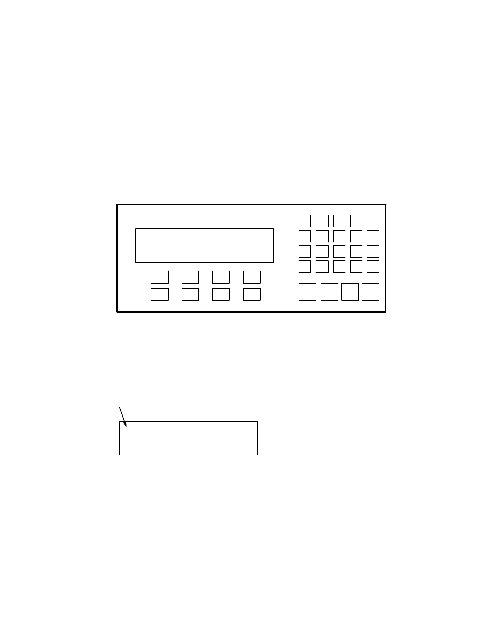
A blinking “L” will appear in the first character position on the display status line to alert all operators that the output is locked.
If another panel attempts to make a switch, the display will indicate the name of the panel that locked the output.
Figure 6−13.
LVTR1 VT1L VT1R VT1T
BLK BARS VTR1 VTR2
Lock symbol
To Unlock an Output
The panel that locked an output is used to unlock the output.
To unlock the output, press LOCK. The display menu line will be cleared and the LOCK prompt will appear (See Figure
6−12). Press TAKE.
