Logical level mapping – Grass Valley VM 3000 System Controllers v.7.4 User Manual
Page 108
Hardware Installation
2−36
VM 3000 Installation and Operating Manual
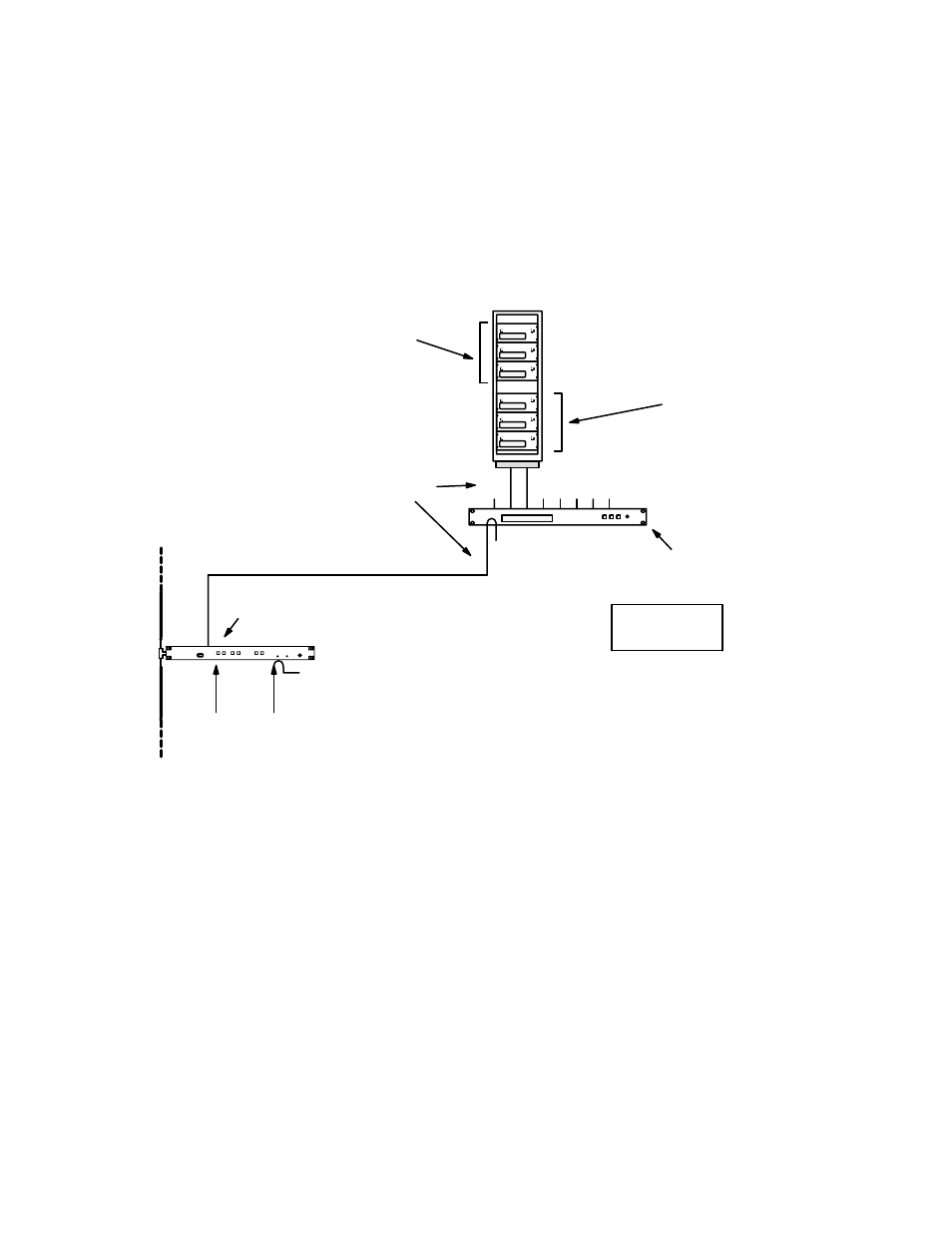
Logical Level Mapping
In these systems, the same physical level number is used on more than one logical level. For example, a switcher could have
video on level 1, left audio on level 2, and right audio also on level 2. In Figure 2−47, a 60 x 60 audio level is being used as
two 60 x 30 switchers, i.e., with half the outputs assigned to the left channel and the other half to the right channel.
This technique can sometimes help reduce overall switcher size, but requires special entries to the Switcher Description table
and the Switcher Outputs table. See Step 9(k) on page 5−37.
Figure 2−47. Logical level mapping (example).
LAN
CC−2010 Matrix cables
CB 3000 Control Buffer
See diagram on
page 2−3 for
cabling details.
Physical level 1
60 x 60 video
Physical level 2
60 x 60 audio
used as
60 x 30 Left
and
60 x 30 Right
House sync
required for
vertical inter-
val switching.
See pg. 2−110
House time
code
(optional).
See pg.
Crosspoint Bus port
VM 3000
System
Controller