Software configuration, Switcher size terminology, Entries to the switcher description table – Grass Valley VM 3000 System Controllers v.7.4 User Manual
Page 683: Switcher input/output tables

3−Stage Switching
H−7
VM 3000 Installation and Operating Manual
SOFTWARE CONFIGURATION
Switcher Size Terminology
Switchers have traditionally been described in terms of active inputs and outputs, but also in terms of the anticipated “fully
expanded” or “pre−wired” size. The pre−wired size is the size that can be achieved simply by plugging in additional compo-
nents.
For three−stage switchers, there is also a “configuration” size, which is used in the Switcher Description table.
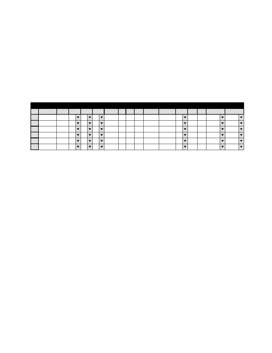
Figure H−6. Switcher Description table for system shown in Figure H−2.
1
Switcher Description
Switcher
MAINROUT
VI
V
RV
MC
M
Board
VM1
#In
512
#Out
1024
PLvL
1
Flw Swit
Flw Name
Dr
B
3 LI
16
3 LO
16
Option
Audio
2
MAINROUT
VM2
512 1024 10
B
16
16
3
MAINROUT
VM3
512 1024 20
B
16
16
4
MAINROUT
VM4
512 1024 30
B
16
16
Name
VIDEO
LEFT
RIGHT
TC
5
6
Entries to the Switcher Description Table
In Figure H−6, the “M Board” column shows the names of four VM 3000 boards, one per logical level. Redundant boards,
if any, are not entered.
The “#In” and “#Out” columns show the correct configuration values for a Venus 512 x 512 three−stage switcher.
The Physical Level entries show the number of the first physical level for each logical level. The software assumes that addi-
tional physical levels will be consecutive. For example, if there are three physical levels in the video switcher, and the first
physical level is “1”, then the second physical level must be set as “2,” etc.
For a Venus 512 x 512 three−stage switcher, the “3LI” and “3LO” entries are always “16.”
SWITCHER INPUT/OUTPUT TABLES
The switcher input table is filled out in the conventional way. In this example (512 x 512), there are 512 entries, with physical
input numbers from zero to 511.
The switcher output table for a Venus 512 x 512 switcher has to reflect the fact that every other output board in the output
stage is not installed; this is done by leaving 16−output “gaps” in the physical output numbering. However, the labels on the
rear−panel connectors do not have any gaps. See page H−8.
