Figure l−2. pinouts for system shown in figure l−1 – Grass Valley VM 3000 System Controllers v.7.4 User Manual
Page 714
Venus DM 400/400A
L−2
VM 3000 Installation and Operating Manual
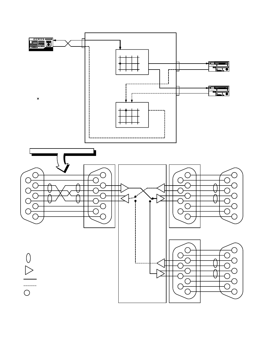
Figure L−1. Example of DM
400/400A Data switching
system.
Tx
Rx
Rx
Tx
Rx
Tx
“EDITOR”
“VCR1D”
“VCR2D”
Forward data
switcher level
“FOR”
03
02
02 04
03
Reverse data
switcher level
“REV”
Port 03
Port 02
Port 04
DM 400/400A
Data Matrix
04
This crosspoint
selected
=
1
6
Rx−
2
7
3
Tx+
8
4
9
5
EDITOR
Twisted pair
Tx−
Rx+
G
G
G
G
S
1
6
Rx−
2
7
3
Tx+
8
4
9
5
Tx−
Rx+
G
G
G
G
S
1
6
Rx−
2
7
3
Tx+
8
4
9
5
Tx−
Rx+
G
G
G
G
S
Path through Forward level of switcher
1
6
Rx−
2
7
3
Tx+
8
4
9
5
Tx−
Rx+
G
G
G
G
S
Port 03
Port 02
VCR 1
†
Path through Reverse level of switcher
1
6
Rx−
2
7
3
Tx+
8
4
9
5
Tx−
Rx+
G
G
G
G
S
1
6
Rx−
2
7
3
Tx+
8
4
9
5
Tx−
Rx+
G
G
G
G
S
Port 04
VCR 2
†
Balanced to unbalanced line conversion
=
=
=
=
Figure L−2. Pinouts for system shown in Figure L−1 .
DM 400/400A Data Matrix
S
Spare
=
†
VCR pinouts may vary. Check VCR manual
=
NOTE NON−STANDARD CABLE !