Network description – Grass Valley VM 3000 System Controllers v.7.4 User Manual
Page 232
Configurator
Network Description Table
5−22
VM 3000 Installation and Operating Manual
Network Description
This table must be used when any of the following are first installed on the LAN:
S VM/SI 3000 System Controllers
S Saturn Master Control Switcher
†
S Philips Broadcast Automation system
S Software Control Panel Suite
‡
S CM 4000 System Controllers
§
0080CE010100
Redundant
2
Network Description
Board Name
VM1
0080CE010101
VM
Address
3
SI1
SI
0080CE010102
1
Type
Address
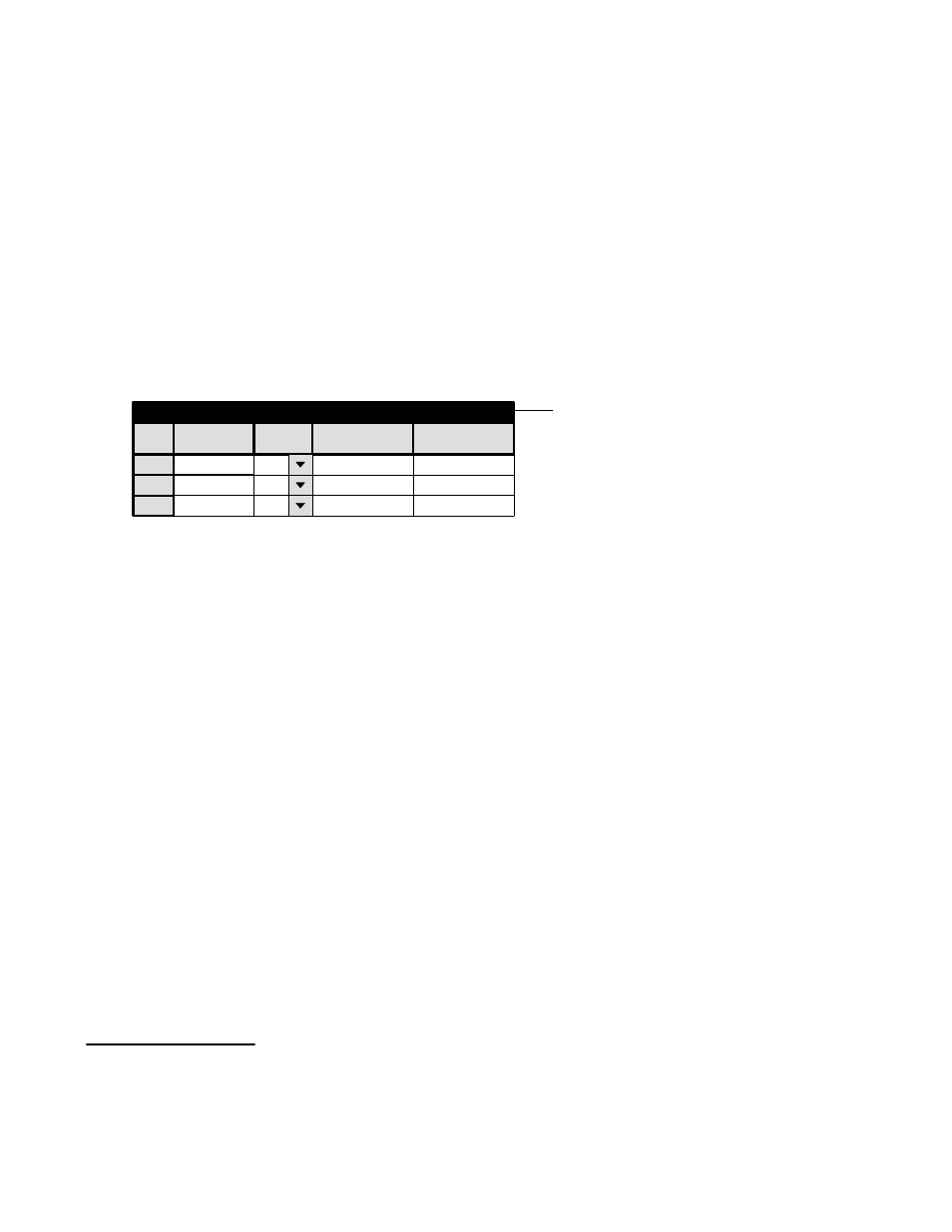
Figure 5−17. Network description (example).
Password
Network Description
Serial Protocol
Control Panel Sets
Machines
TCS−1 Device Codes
Status Display Header
Tally
Exclusion
Each board is given a user−specified name up to eight characters in length. The system is told which type it is, and the Ethernet
address, in hexadecimal, as shown on the back of the controller chassis. The Ethernet address was furnished by Xerox Corp.
and is unique world−wide. If the board is redundant, the address of the second unit is entered.
Important: Row numbers on Jupiter tables are used as the “logical” numbers for devices. Changing the row num-
ber of an existing device (by inserting/deleting a new controller board in the middle of the table, for example) will
disrupt control of the system, requiring controller boards to be memory−cleared and reset (see “Clearing Bat-
tery−Protected Memory” in Appendix B). One way to avoid this interruption is to add new devices at the end of
tables.
†
Saturn configuration instructions are described in the Saturn Installation and Operating manual.
‡
Applies only when Software Control Panel is used for machine control. For more information, see Section 7.
§
For details about CM 4000 applications, see the CM 4000 Installation and Operating Manual.