Vm/si 3000 controller boards – Grass Valley VM 3000 System Controllers v.7.4 User Manual
Page 742
Status and Error Codes
VM 3000 Installation and Operating Manual
S−2
VM/SI 3000 CONTROLLER BOARDS /
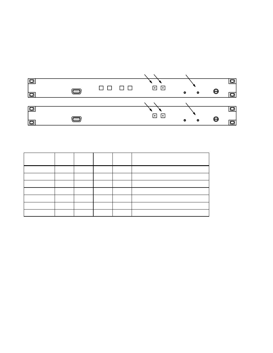
Current board status is reflected using the status LEDs on the front panel of the VM 3000 and SI 3000. The three main status
LEDs on the front panel of the VM 3000 and SI 3000 are clearly marked (from left to right) “ACTIVE,” “FAULT,” and
“ALARM.” On the VM 3000 and SI 3000, Alarm Relay contacts are on the rear panel. The LED and Relay functions are
described in the table below.
Figure S−2. Board status indicators.
VM 3000
SI 3000
UP
DOWN
NEXT
SELECT
ACTIVE
FAULT
FAULT
CLEAR
ACTIVATE
POWER
ALARM
PROBE
ACTIVE
FAULT
FAULT
CLEAR
ACTIVATE
POWER
ALARM
PROBE
State
Active
LED
Fault
LED
Alarm
LED
Alarm
Relay
Description
STARTUP
ON
ON
ON
ON
Boot ROM code is running
LOADER
OFF
OFF
ON
ON
Check/Program lists, system
SYSTEM
OFF
ON
OFF
ON
Loader done, ready to start
STARTUP
ON
ON
OFF
ON
Starting applicable tasks
ACTIVE
ON
OFF
OFF
OFF
Board running, Active mode
STANDBY
OFF
OFF
OFF
OFF
Board running, Standby mode
FATAL
OFF
ON
ON
ON
Fatal error, board halted
Figure S−3. LED definitions.