Mi 3040 general purpose / tally interface entries, Machine interface applications, Tally interface applications – Grass Valley VM 3000 System Controllers v.7.4 User Manual
Page 327: P. 5−117)
Configurator
MPK Devices
5−117
VM 3000 Installation and Operating Manual
MI 3040 GENERAL PURPOSE / TALLY INTERFACE ENTRIES
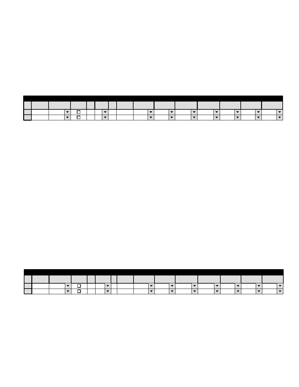
Machine Interface Applications
The following example applies to two “MI 3040/2s,” that is, MI 3040s configured to control two functions (Play and Stop)
on each of 20 machines. For system drawings, see pages 2−100 and 2−103.
Figure 5−92. Entries for MI 3040s used for machine control.
MI1
MI2
MI−3040/2
MI−3040/2
1
MPK Devices
MPK
Expansion
Pass
Board
Port
5
Address
00000026
Input Sets
Output Sets
Level Set
Overide Set
Sequence Set
2
5
00000041
Devices
word
In Panel
Out Panel
SI1
VM1
Device
Type
Entries will also be required on the Machine Control table (page 5−157.)
Tally Interface Applications
When an MI 3040 is configured as an “MI 3040/T,” that is, configured to control tally lights (as shown on page 2−113 and
following), an entry similar to that shown as row 1 in Figure 5−93 will be required. If there is more than one MI 3040, an entry
with a unique Device Name will be required for each. This entry is the source of the Device Name for the MI 3040 and this
same name must be selected on the Tally Dependency table (page 5−178).
If the tally system is being used in connection with a Saturn Master Control Switcher or a MCS 2000 Master Control Switcher,
an additional entry will be required to allow the Jupiter system to gather tally information from the MCS. This entry will be
similar to row 2 in Figure 5−93. The Device Name (“MCS_TLY” in this example) must also be selected on the Tally Depend-
ency table (page 5−178). If more than one master control switcher is in the system, there must be an entry for each—for exam-
ple, with Device Names such as “MCS_TLY1,” “MCS_TLY2,” etc. For Saturn, the “Board” is always the name of the video
processor; the MPK “Port” is always “1” (this is true even if the MPK port is not physically connected to the MI−3040). For
an MCS 2000, the “Board” is the name of the device that is the source of the TCS 2 bus, i.e., the device that is connected to
the Machine Control port of the EC 2000 Control Electronics.
Figure 5−93. Entry for MI 3040 used for tally.
TALLY1
MCS_TLY
MI−3040/T
MCS_TALY
SI1
DVP−1
5
1
00000026
1
MPK Devices
MPK
Expansion
Pass
Board
Port
Address
Input Sets
Output Sets
Level Set
Overide Set
Sequence Set
2
Devices
word
In Panel
Out Panel
Device
Type
External Control of Saturn Master Control Switcher (“MI 3040IO” application)
Using the MI 3040 General Purpose / Tally Interface, an external device can transmit commands to, and receive status from,
a Saturn Master Control Switcher. In this application, the MI 3040 is configured in software as an “MI 3040IO.” For more
information, refer to “MI 3040IO” in the Saturn Installation and Operating manual.