Software configuration – Grass Valley VM 3000 System Controllers v.7.4 User Manual
Page 201

Hardware Installation
2−129
VM 3000 Installation and Operating Manual
CONNECTION TO SYSTEMS WITH JUPITER−CONTROLLED ROUTER ONLY
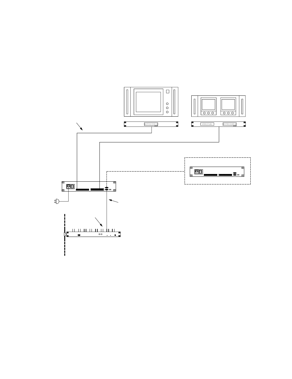
SlimLine UMDs are connected to the Jupiter VM/SI 3000 through a SlimLine Controller, which has RJ45 ports for Cat 5
Ethernet cable connection to 16 UMDs. Power is provided to the UMDs through the Cat 5 cables. See Figure 2−143.
Figure 2−143. SlimLine UMD
Status Display installation.
Up to 16 UMDs per SlimLine controller
MPK bus
Serial data cable (see page 2−109)
Cat 5 cable
(see Note 2 on page 2−128)
SlimLine UMD Controller
MPK bus loop to additional SlimLine Controllers
AC
power
Serial ports
VM/SI 3000
LAN
Software Configuration
Under monitor status displays must be identified as MPK devices. See page NO TAG.
If SlimLine UMD tally light operation is needed, additional configuration will be required:
S For the Jupiter Standard Tally application, there must be an MPK table entry for an “MI 3040/T” whether it is
physically present or not (see page 5−121). Entries to the Tally Relay and Tally Dependency tables will also be
needed (see pages 5−172 and 5−178).
