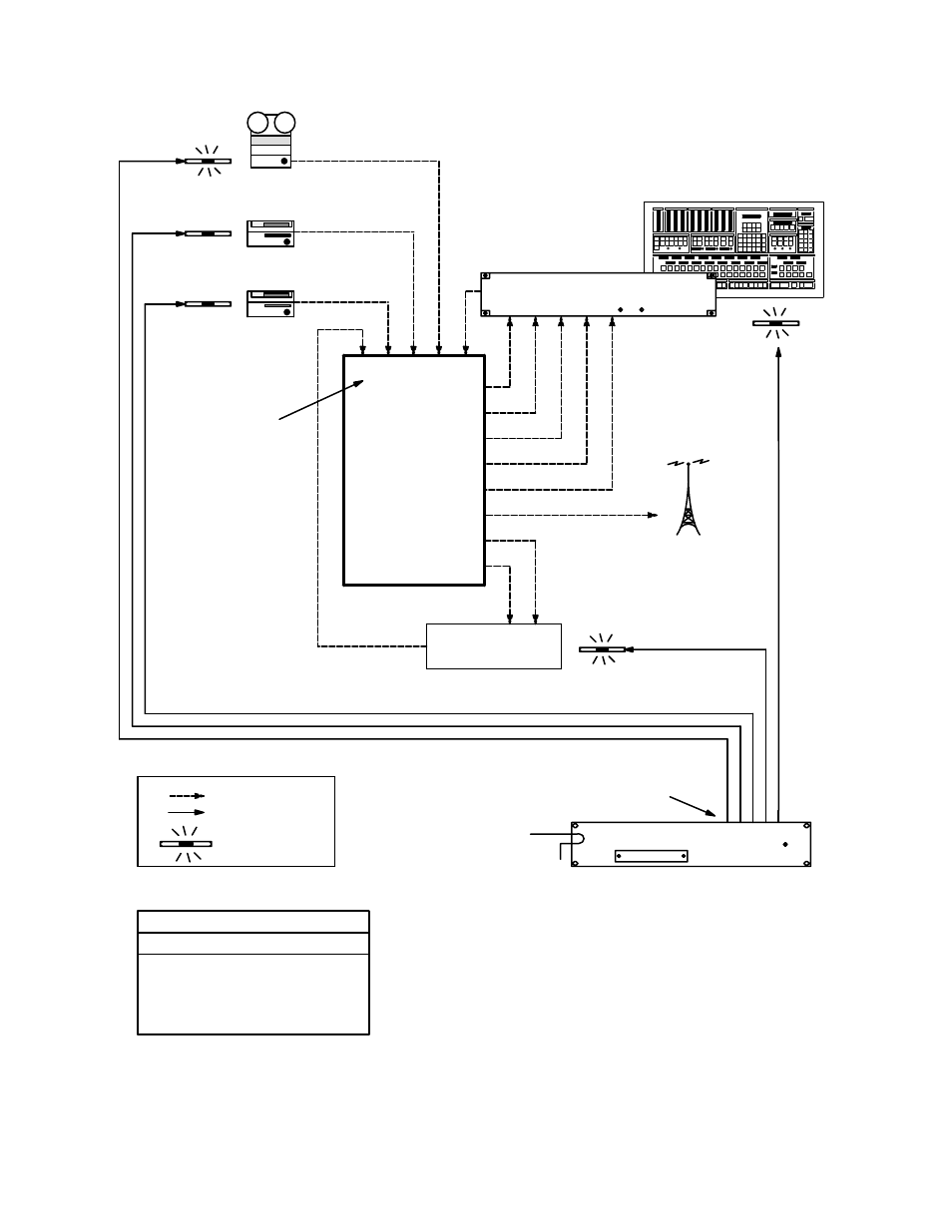
Figure 5−154 – Grass Valley VM 3000 System Controllers v.7.4 User Manual
Page 386

Configurator
Tally
5−176
VM 3000 Installation and Operating Manual
MPK bus
MI−3040/T
“TALLY1”
Relays
Transmitter
Video and audio
Jupiter control lines
Routing
switcher
Production switcher
Tally light
Master control switcher
VC02 VT01
PRD
MCS
VC01
2
0 1
3 4
Input names
Tally Device Relay
Logical Input
1
TALLY1
0
VT01
2
TALLY1
1
VC02
3
TALLY1
2
VC01
4
TALLY1
3
PRD
5
TALLY1
4
MCS
Tally Relay
Ï
Ï
ÏÏ
ÏÏ
Ï
Ï
Ï
Ï
Ï
ÏÏ
Ï
Ï
ÏÏ
Ï
ÏÏ
Ï
Ï
Ï
Ï
ÏÏ
ÏÏ
Ï
Ï
Ï
Ï
ÏÏ
Ï
ÏÏ
Ï
Ï
Ï
Ï
Ï
ÏÏ
Ï
ÏÏ
Ï
Ï
Ï
Ï
Ï
Ï
Ï
Ï
Ï
Ï
Ï
Ï
Ï
ÏÏ
Ï
Ï
Ï
ÏÏ
Ï
Ï
Ï
ÏÏ
ÏÏ
Ï
Ï
Ï
Ï
Ï
Ï
ÏÏ
Ï
Ï
Ï
Ï
Ï
Ï
Ï
Ï
ÏÏ
ÏÏ
ÏÏ
ÏÏ
ÏÏ
Ï
Ï
Ï
Ï
Ï
Ï
Ï
Ï
Ï
Ï
ÏÏ
ÏÏ
Ï
Ï
Ï
ÏÏ
ÏÏ
ÏÏ
Ï
Ï
Ï
Ï
Ï
Ï
Ï
Ï
Ï
Ï
Ï
Ï
Ï
Ï
Ï
Ï
Ï
Ï
Ï
Ï
ÏÏ
ÏÏ
Ï
Ï
Ï
Ï
ÏÏ
ÏÏ
Ï
Ï
Ï
Ï
Ï
Ï
Ï
Ï
Ï
Ï
Ï
ÏÏ
ÏÏ
ÏÏ
Ï
Ï
Ï
Ï
ÏÏ
ÏÏ
ÏÏ
ÏÏ
Ï
Ï
Ï
ÏÏ
ÏÏ
ÏÏ
Ï
Ï
Ï
Ï
Ï
ÏÏ
Ï
Ï
ÏÏ
ÏÏ
Ï
Ï
Ï
ÏÏ
Ï
Ï
Ï
Ï
Ï
Ï
Ï
ÏÏ
Ï
Ï
Ï
Ï
Ï
Ï
Ï
ÏÏ
Ï
Ï
Ï
Ï
Ï
Ï
Ï
Ï
Ï
Ï
Ï
Ï
Ï
Ï
Ï
Ï
Ï
Ï
Ï
Ï
Ï
Ï
Ï
Ï
Figure 5−154. Tally system with Jupiter−controlled router, Saturn
(or non−Saturn) master control, production switcher, and indirect
feed to transmitter. Equipment shown corresponds to table at left.
