Grass Valley VM 3000 System Controllers v.7.4 User Manual
Page 307

Configurator
CP Output Set
5−97
VM 3000 Installation and Operating Manual
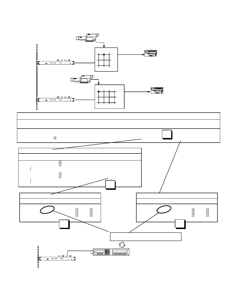
Figure 5−76. CP Output Set and CP Level Set requirements for multiple switcher installations. See page 5−96 for discussion.
VT01
Cam9 Cam1
VT20 VT01
CAM1
CP 3000/E
“STUCP”
VT20
CAM9
VM 3000
TVS/TAS 2000
“NEWSROUT”
Venus
“MAINROUT”
MPK
Device
Devices
Type
Exp Pw Mode
Board
Port
Address
In Set
In Panel
Out Set
Out Panel
Lev Set
Over Set
Seq Set
1
STUCP
CP−3000
L
S1
10
00000014
KXYZ−INP
KXYZ−OUT
KXYZ−LEV
KXYZ−OVE
MPK Devices
Level Set — KXYZ−LEV
1
VID
VIDEO (MAINROUT)
2
LEFT
LEFT (MAINROUT)
3
RGHT
RIGHT (MAINROUT)
Mnemonic
Level
Break
Switch
Output Set — KXYZ−OUT
1
VTR
1
VT01
VT01
[BLANK]
2
VTR
2
VT02
VT02
[BLANK]
VCR
20
VT20
VT20
2000−LEV
VCR
21
VT21
VT21
2000−LEV
Auto
Logical
Category
Entry
Mnem
Mnemonic
Output
Level Set
Button
Level Set — 2000−LEV
1
VID
VIDEO (NEWSROUT)
2
LEFT
LEFT (NEWSROUT)
3
RGHT
RIGHT (NEWSROUT)
Mnemonic
Level
Break
Switch
Status
Output
1
VM 3000
VM 3000
“’VM1”
2
3
4
