Mi 3040 general purpose interface entries, Mc 3040 (mi 3040) entries – Grass Valley VM 3000 System Controllers v.7.4 User Manual
Page 367

Configurator
Machine Control Table
5−157
VM 3000 Installation and Operating Manual
MI 3040 GENERAL PURPOSE INTERFACE ENTRIES
Use of an MI 3040 for parallel control of machines requires entries to the MPK Devices table (as described on page 5−117)
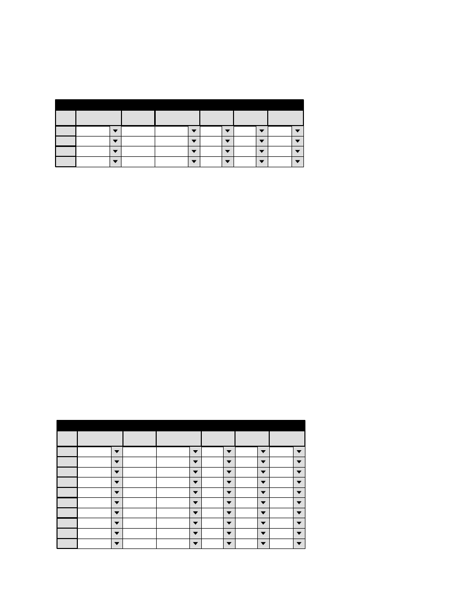
and to the Machine Control table (Figure 5−136).
1
Machine Control
Device Name
Device Type
Delegation
In/Out
Associated
2
Mi1
MI−3040/2
In
CRT2
3
Mnemonic
CRT2
MI2
MI−3040/2
In
VT07
MI2
MI−3040/2
In
VT08
MI1
MI−3040/2
In
CRT1
4
Group
Name
VT07
VT08
CRT1
Figure 5−136. Example of entries for
machines controlled by MI 3040s.
There are two MI 3040/2s shown in this example: one controls a pair of VTRs and the other a pair of audio cart machines.
The Device Names for the MI 3040s were already entered on the MPK Devices table; they are selected here from the drop−
down menu.
The Mnemonic column is used to create a mnemonic for each machine connected to the MI 3040. This is the source for the
machine name that appears on control panels.
Note: The Jupiter system identifies each machine according to the order of entry on this table. Therefore this order
must be the same as the hardware connections to the MI 3040. In this example, VT07 would be connected to ports
0 and 1 of the MI−3040 assigned to SI1; VT08 would be connected to ports 2 and 3 of the MI 3040 assigned to
SI1 (for system drawings, see pages 2−100 and 2−103). Audio cart CRT1 would be connected to ports 0 and 1 of
the MI 3040 connected to VM1; CRT2 would be connected to ports 2 and 3 of the MI 3040 connected to VM1
(see page 2−103).
MC 3040 (MI 3040) ENTRIES
The following example applies to non−Grass Valley control panels or computers connected to an “MC−3040/4,” that is, an
MI 3040 configured for four functions (Play, Stop, Ready, and Cue) on each of 10 control panels or devices.
If there is only one control panel (or computer), only a one−row entry would be required for this table.
Note: The Jupiter system identifies each control panel according to the order of entry on this table. Therefore this
order must be the same as the hardware connections to the MC 3040.
For system drawings, see pages 2−104 and 2−107. An entry must also be made to the MPK Devices table (page 5−118).
1
Machine Control
Device Name
Device Type
Delegation
In/Out
Associated
Mnemonic
MC3040
MC−3040/4
Out
PRDA
Group
Name
VT01
2
MC3040
MC−3040/4
Out
PRDB
VT02
3
MC3040
MC−3040/4
Out
PRDC
VT03
4
MC3040
MC−3040/4
Out
PRDD
VT10
5
MC3040
MC−3040/4
Out
PRDE
CART
6
MC3040
MC−3040/4
Out
PRDF
MC3040
7
MC3040
MC−3040/4
Out
PRDG
MC3040
8
MC3040
MC−3040/4
Out
PRDH
MC3040
7
MC3040
MC−3040/4
Out
PRDI
MC3040
8
MC3040
MC−3040/4
Out
PRDJ
MC3040
Figure 5−137. Example entries for
MC 3040.
