Remote control via modem, Jupiter configuration – Grass Valley VM 3000 System Controllers v.7.4 User Manual
Page 180
Hardware Installation
2−108
VM 3000 Installation and Operating Manual
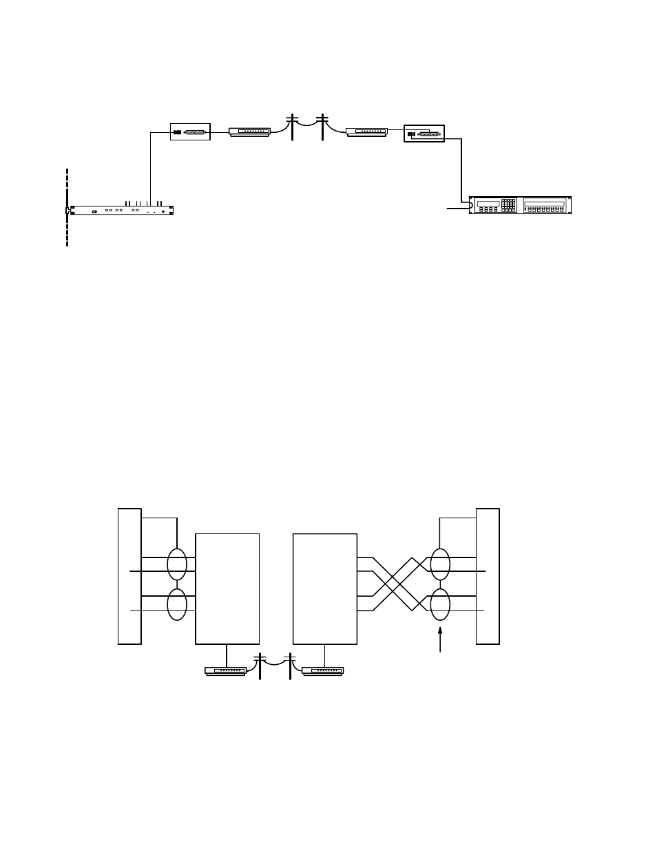
REMOTE CONTROL VIA MODEM
VM/SI 3000 (VM
3000 shown)
Serial (MPK) bus
operating at 2400
baud
Jupiter control panel
Telephone line
Modem
Modem
Figure 2−122. Modem control installation.
LAN
RS−422/232
converter
RS−422/232
converter
The Jupiter system can be controlled through a modem connection using:
S A CP 3000 control panel equipped with a 1200/2400 baud PROM (FCS−3306/1/2, part no.
45−043114−01A/B). These products are described in separate documents, part no. 04-883306-001 (1200 baud
version) and 04-883306-002 (2400 baud version).
S An MPK control panel that allows baud rate selection on the front panel (e.g., CP 3800A, CP 3830, CP 3808,
CP 3832, CP 3864 etc.). These products are described later in this manual.
The modems used in such a system should be connected to the Jupiter hardware through RS−232/422 converters. See Figures
2−122 and 2−123. The only modem supported for this application is the Motorola V.3229, which is available from Black Box
Corp. or NetLink Technology, Inc. Two RS−232/422 Converters are recommended: 1), the Black Box IC107A RS−232 >
RS−422 Converter, and 2) the Integrity Instruments 422−25I with external power supply. For instructions that apply specifi-
cally to these third−party items, please refer to Grass Valley Field Engineering Bulletin 04-047604-081.
Figure 2−123. Generalized modem wiring.
1
2
3
7
8
P1
DB9P
(male)
Shield
Green
Black
White
Red
Frame ground
Receive A (−)
Transmit A (−)
Receive B (+)
Transmit B (+)
Transmit B (+)
Transmit A (−)
Receive B (+)
Receive A (−)
VM 3000
control board
RS−422/232
converter
1
2
3
7
8
P1
DB9P
(male)
Green
Black
White
Red
Frame ground
Receive A (−)
Transmit A (−)
Receive B (+)
Transmit B (+)
Transmit B (+)
Transmit A (−)
Receive B (+)
Receive A (−)
Twisted pairs
Jupiter control
panel
RS−422/232
converter
Shield
Modem
Modem
Jupiter Configuration
Using the Serial Protocol table, change to the appropriate baud rate for the port that is connected to the modem. Only one
control panel can be defined on a port that is connected to a modem. For more information, see page 5−25.