Grass Valley VM 3000 System Controllers v.7.4 User Manual
Page 191
Hardware Installation
2−119
VM 3000 Installation and Operating Manual
MPK bus
MI 3040
General Purpose/
Tally Interface
+5 V utility
connection
Ground utility
connection
40 relays.
See Fig.
2−137.
Transmitter
Video and audio
Jupiter Control lines
Jupiter−controlled
router
Production
switcher
40 opto−iso-
lators. See
Fig. 2−138.
Tally light
One connection per tally light.
100 V, 300 mA max.
Sources
Equal number
of connections
Saturn/MCS master
control switcher
Î
Î
Î
Î
ÎÎ
ÎÎ
Î
Î
Î
Î
Î
Î
Î
Î
Î
Î
ÎÎ
Î
Î
Î
ÎÎ
ÎÎ
Î
Î
Î
ÎÎ
Î
Î
Î
ÎÎ
ÎÎ
Î
Î
Î
Î
ÎÎ
Î
ÎÎ
Î
Î
Î
ÎÎ
Î
Î
Î
ÎÎ
Î
Î
Î
Î
ÎÎ
Î
Î
Î
ÎÎ
Î
Î
Î
Î
Î
Î
ÎÎ
ÎÎ
Î
Î
Î
ÎÎ
Î
Î
Î
Î
Î
Î
Î
Î
Î
Î
Î
Î
ÎÎ
Î
Î
ÎÎ
Î
Î
Î
Î
ÎÎ
Î
Î
Î
Î
ÎÎ
Î
ÎÎ
ÎÎ
Î
Î
ÎÎ
Î
Î
Î
ÎÎ
ÎÎ
ÎÎ
ÎÎ
Î
Î
Î
Î
Î
Î
Î
Î
Î
Î
Î
Î
ÎÎ
ÎÎ
ÎÎ
Î
Î
Î
ÎÎ
ÎÎ
ÎÎ
ÎÎ
Î
Î
Î
Î
ÎÎ
ÎÎ
Î
Î
Î
Î
ÎÎ
ÎÎ
Î
Î
Î
Î
Î
Î
Î
Î
Î
Î
Î
Î
Î
Î
Î
Î
Î
Î
Î
Î
Î
Î
Î
Î
Î
Î
Î
Î
Î
Î
Î
Î
Î
Î
ÎÎ
ÎÎ
ÎÎ
ÎÎ
Î
Î
Î
Î
Î
Î
Î
Î
Î
Î
Î
Î
Î
Î
Î
Î
Î
Î
Î
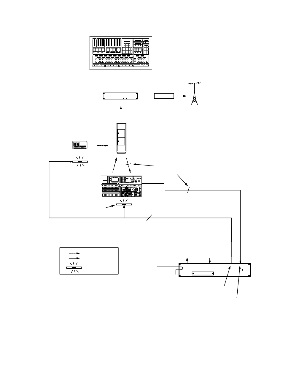
Figure 2−132. Multi−switcher tally system with production switcher, Jupiter−con-
trolled router, Saturn/MCS master control, and direct feed to transmitter.
DIRECT
Switcher
tally relays
Saturn/MCS
processor