Figure 5−139 – Grass Valley VM 3000 System Controllers v.7.4 User Manual
Page 371
Configurator
Delegation Groups
5−161
VM 3000 Installation and Operating Manual
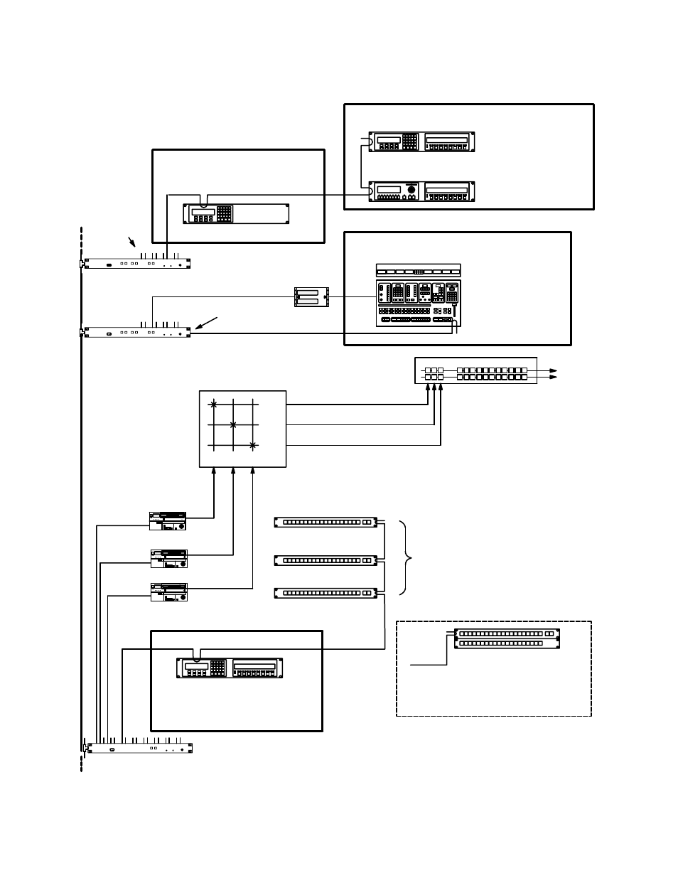
Figure 5−139. Delegation system (example).
Group “STU”
Group “MCS”
CP−3000
Group “ENG”
Group “TAPE”
MC−3020D Machine Delegate Panels
(see Figure 5−140 for button labels)
“VT01”
“VC01”
“VC02”
MC−3000/E
Device name “STUMC”
MCS−2000
Device name “MCS”
Device name “ENGCP”
CP−3000/E
Device name “TAPECP”
“DELEVT01”
“DELEVC01”
“DELEVC02”
CP−3000/E
Device name “STUCP”
VT01 VC01 VC02
PRDA
PRDB
PRDC
Routing
Switcher
Production switcher
A B C
Alternative central control arrangement
See page 2−76 for hardware installation
VM 3000
“VM2”
Party line
connection
Serial ports
SI 3000
“SI1”
VM 3000
“VM1”
This manual is related to the following products: