Table (figure 5−141, 5−162). the order, Control menu (figure 5−142 o – Grass Valley VM 3000 System Controllers v.7.4 User Manual
Page 372

Configurator
Delegation Groups
5−162
VM 3000 Installation and Operating Manual
ENG
MCS
STU
TAPE
All
groups
No
groups
Master Control
group
Studio
group
Tape Room
group
Engineering
Room group
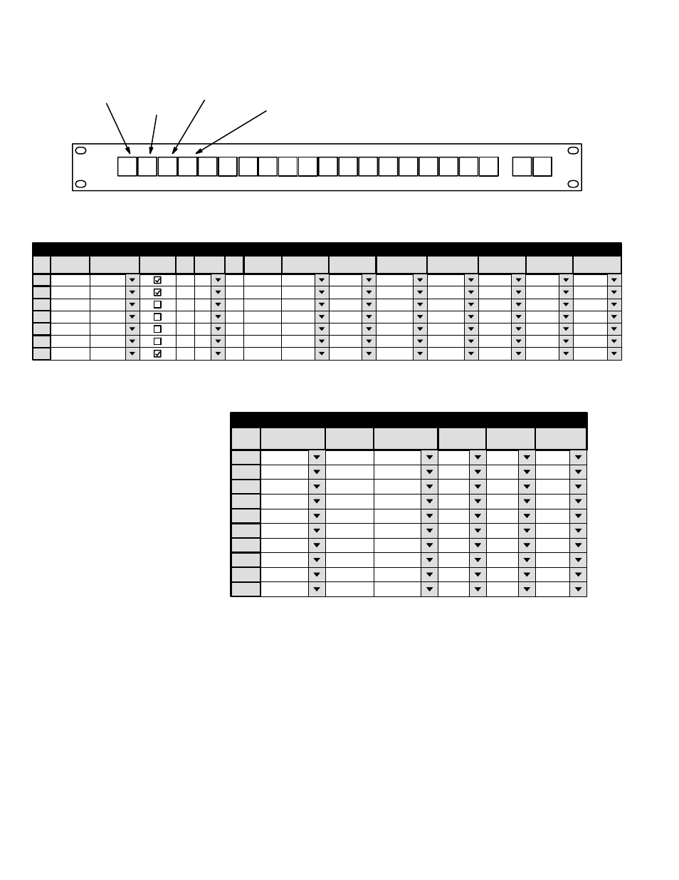
Figure 5−140. MC 3020D Group Delegation
Panel for system shown in Figure 5−139.
MPK Devices
MPK
Expansion
Pass
Board
Port
Address
Input Sets
Output Sets
Level Set
Overide Set
Sequence Set
Devices
word
In Panel
Out Panel
1
STUCP
CP−3000
VM1
6
00000014
KXYZ−INP
STU−OUT
KXYZ−LEV
KXYZ−OVE
2
STUMC
MC−3000
VM1
6
00000016
3
ENGCP
CP−3000
VM1
6
00000013
KXYZ−INP
KXYZ−OUT
KXYZ−LEV
KXYZ−OVE
4
DELEVT01
MC−3020D
SI1
6
00000017
VT01−OUT
5
DELEVC01
MC−3020D
SI1
6
00000018
VC01−OUT
6
DELEVC02
MC−3020D
SI1
6
00000019
VC02−OUT
7
TAPECP
CP−3000
SI1
6
00000012
KXYZ−INP
VTR−OUT
KXYZ−LEV
KXYZ−OVE
Figure 5−141. MPK Device menu for system shown in Figure 5−139. In the alternative “central control” arrangement, there would be
only one MC 3020D entry, and the indicated “Out Set” would be a list of machines assigned to the expansion panel (see page 5−85).
Device
Type
8
Machine Control
Device Name
Device Type
Delegation
In/Out
Associated
9
STUCP
CP−3000E
STU
Out
10
Mnemonic
STUCP
VT01
Sony Mch
In
VT01
VC01
Sony Mch
In
VC01
VC02
Sony Mch
In
VC02
2
Group
Name
VT01
VC01
VC02
STUMC
MC−3000E
STU
Out
PRDA
STUMC
3
MCS
TCS1−CP
MCS
In
MCS
1
STUMC
MC−3000E
STU
Out
PRDB
STUMC
4
STUMC
MC−3000E
STU
Out
PRDC
STUMC
5
ENGCP
CP−3000E
ENG
ENGCP
6
TAPECP
CP−3000E
TAPE
TAPECP
7
Figure 5−142. Machine Control table for system shown in Figure 5−139.
