See figure 2−37, See figure 2−38 – Grass Valley VM 3000 System Controllers v.7.4 User Manual
Page 102
Hardware Installation
2−30
VM 3000 Installation and Operating Manual
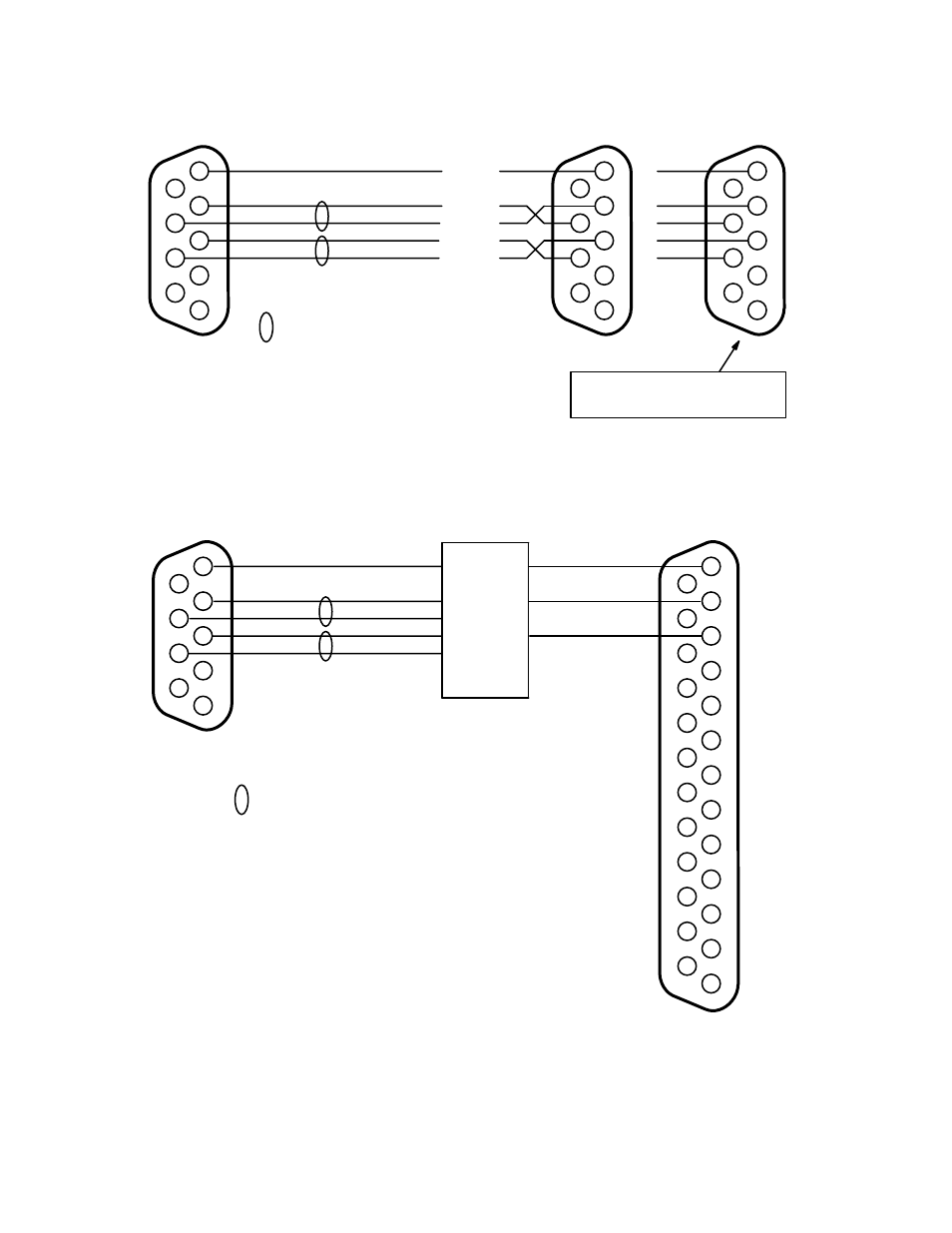
Figure 2−37. Cable for connecting VM 3000 to UDI−1B RS−422 port.
1
6
R−
2
7
3
T−
8
4
9
5
R+
T−
to VM 3000
serial port
UDI−1B
RS−422 Port
G
Ground
R−
Receive minus
R+
Receive plus
T+
Transmit plus
T−
Transmit minus
DB9P
(male)
DB9P
(male)
= twisted pair
1
6
2
7
3
8
4
9
5
T+
R−
R+
T+
G
G
R+
T−
1
6
2
7
3
8
4
9
5
R−
T+
G
UDI pinouts may vary − field reports
indicate that a straight−through
cable should be tried first.
Figure 2−38. Cables for connecting VM 3000 to UDI−1B RS−232 port.
1
6
R−
2
7
3
T−
8
4
9
5
R−
T+
to VM 3000
serial port
G
Ground
R−
Receive minus
R+
Receive plus
T+
Transmit plus
T−
Transmit minus
DB9P
(male)
= twisted pair
T+
R+
R+
T−
G
G
Tx
Rx
DB25P
(male)
1
2
3
4
5
G
6
7
8
9
10
11
12
13
14
15
16
17
18
19
20
21
22
23
24
25
UDI−1B
RS−232 Port
Rx
Tx
G
RS−422/232
converter
This manual is related to the following products: