Software configuration – Grass Valley VM 3000 System Controllers v.7.4 User Manual
Page 160
Hardware Installation
2−88
VM 3000 Installation and Operating Manual
Model 200 production switcher with E−MEM Effects Memory
In systems where a Jupiter−controlled router is used to provide sources for a Model 200 switcher, the Jupiter control system
can be used to select sources for the Model 200 and instructed to remember those sources. Later, a single E−MEM command
can be used to restore the sources to the production switcher.
In this application, the Model 200 controls the routing switcher as a “peripheral device,” using the Dual Serial Adapter Port
1 connected to a VM/SI 3000. The serial connection is referred to in Model 200 documentation as the Peripheral Bus and by
Jupiter as a GVG200 bus:
With the STREAMLINE option, the Model 200 switcher can be set to address a particular peripheral, such as a character gener-
ator [or routing switcher], during E−MEM Effects Memory learns and recalls. When a [production] switcher effect is learned
into an E−MEM register, the Model 200 sends a command over the peripheral bus to the peripheral device [VM/SI 3000] tell-
ing it to learn its current status [routing switcher status] into a memory register of its own. Later, when the same Model 200
E−MEM register is recalled, the 200 will send a command over the peripheral bus to instruct the peripheral device to recall
the effect [routing switcher status] that it had previously stored in its own memory.
†
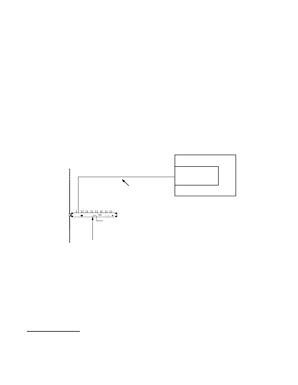
For hardware installation, see Figure 2−104.
GVG200 bus (“Peripheral Bus”)
LAN cable
VM/SI 3000
Sync ref. See
Model 200 Switcher
Dual Serial
Adapter Port 1
(option)
See page 2−109 for a
description of this cable
Figure 2−104. Connections to Model 200 switcher.
Note: Due to a Jupiter software limitation, connecting Peripheral devices in addition to the single VM/SI is not
recommended. For more information, see page 5−130.
Software Configuration
For the VM/SI/SC 3000 port being used, “GVG200” protocol is set on the Serial Protocol table (see page 5−27). The produc-
tion switcher is identified as a control device on the MPK Devices table, and special CP Input and Output Sets must be created
(see page 5−130).
†
Model 200 Peripheral Interface II Protocol and Dialect (Grass Valley Group Manual Number TP0424−00, June 1988), p.
1−2.