Tally dependency, Overview, And 5−178) – Grass Valley VM 3000 System Controllers v.7.4 User Manual
Page 388
Configurator
Tally
5−178
VM 3000 Installation and Operating Manual
TALLY DEPENDENCY
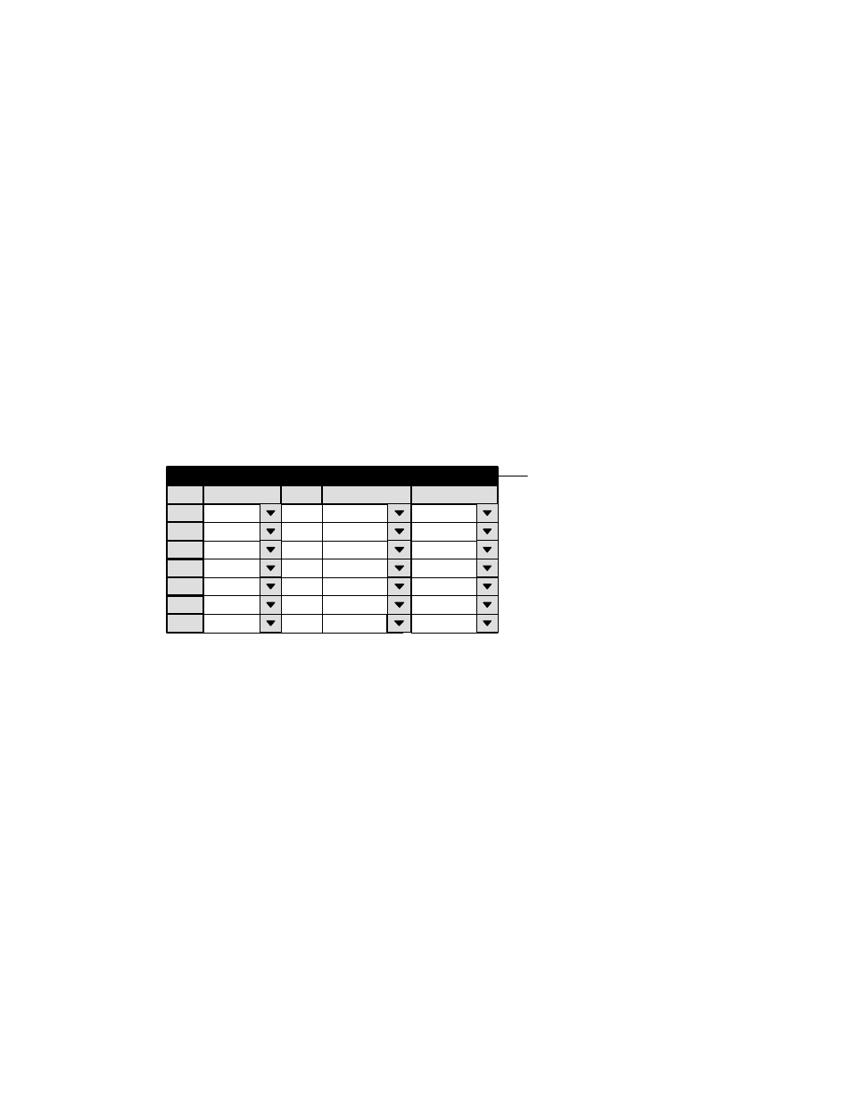
Figure 5−156. Tally Dependency table (example).
1
Tally Dependency
Tally Device
MCS_TLY
Opto
0
Logical Output
MAIN−A
Tally
2
3
MCS_TLY
1
MAIN−B
MCS_TLY
2
KEYINS1
4
5
MCS_TLY
3
KEYINS2
MCS_TLY
4
MIXINS1
6
MCS_TLY
5
MIXINS2
7
MCS_TLY
6
BYPASS
Password
Control Panel Sets
Level set
Machines
TCS−1 Device Codes
Status Display Header
Tally
Exclusion
OVERVIEW
This table must be used when an MI 3040 has been configured to operate as a “MI 3040/T,” i.e., for operation with tally lamps.
The Tally Relay table must also be used (page 5−172).
Note 1: The Jupiter Tally system described in this manual cannot tally sources that are wired directly to a Saturn
internal matrix. If the Saturn is equipped with an internal matrix, the Saturn Tally system is available (but cannot
be connected to the Jupiter tally system). Please refer to the Saturn Installation and Operating manual for additional
information.
Note 2: The Tally Dependency table is also used for systems with under monitor status displays, when input mne-
monics must be tracked back through a master control or production switcher. See page NO TAG.
The table has two basic purposes: first, to establish the identity of the main output of the system (the output being fed by the
tallied source); and second, to allow the Jupiter system to track sources through switchers other than the routing switcher.
Whatever source is feeding the main output (usually a transmitter) is tallied. When the main output is fed directly from the
routing switcher, it is referred to as an unqualified output; a sample entry is shown in Figure 5−157.