Grass Valley VM 3000 System Controllers v.7.4 User Manual
Page 365
Configurator
Machine Control Table
5−155
VM 3000 Installation and Operating Manual
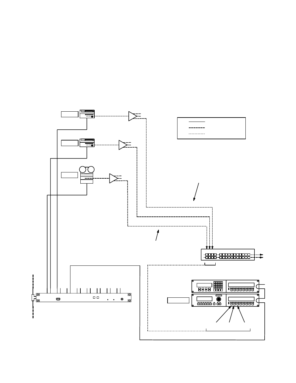
LINKAGE FOR MACHINES THAT DO NOT ENTER THE ROUTING SWITCHER
In some cases, machines may be wired directly to one destination, or to several destinations through distribution amplifiers
only (see Figure 5−134). Although these machines do not pass through the routing switcher, it is still possible to use switcher
control panels to establish linkages. In order to do this, imaginary switcher input and output names must be used as pointers
on the Machine Control menu. These names, along with imaginary physical I/O numbers, must be entered on the Switcher
Input and Output tables (pages 5−44 and 5−51). Also, the physical I/O numbers must be within the size range set on the
Switcher Description menu (page 5−31).
Figure 5−134. Machine control linkage in system without routing switcher.
PRDC
PRDB
PRDA
Production switcher
A B C D
“VT01”
“VC01”
“VC02”
“TapeMC”
MC−3000
CP−3000
VC02
VC01
VT01
SELECT buttons
video and audio
control lines
software links
Imaginary routing
switcher input
names
Imaginary routing
switcher output
names
VC02
VC01
VT01
SI 3000 “SI1”
3
1
2
6