Utility connections, Fig. 2−138 – Grass Valley VM 3000 System Controllers v.7.4 User Manual
Page 196
Hardware Installation
2−124
VM 3000 Installation and Operating Manual
Utility Connections
+5 V and ground utility connections are provided on the back panel. There are two +5 V connectors, each of which is equipped
with a PCB−mounted 1 amp fuse. The fuse is designed to reset itself automatically.
to external
device
PVA1352
9
10
11
12
13
14
15
16
8
7
6
5
4
3
2
1
8
7
6
5
4
3
2
1
S1
+5V
R1
10K
VBRD (31)
1
U84
F86
[SMT]
3
R9
220
2
3
5
8
RDB (31)
RDA (31)
J2−B9
J2−B8
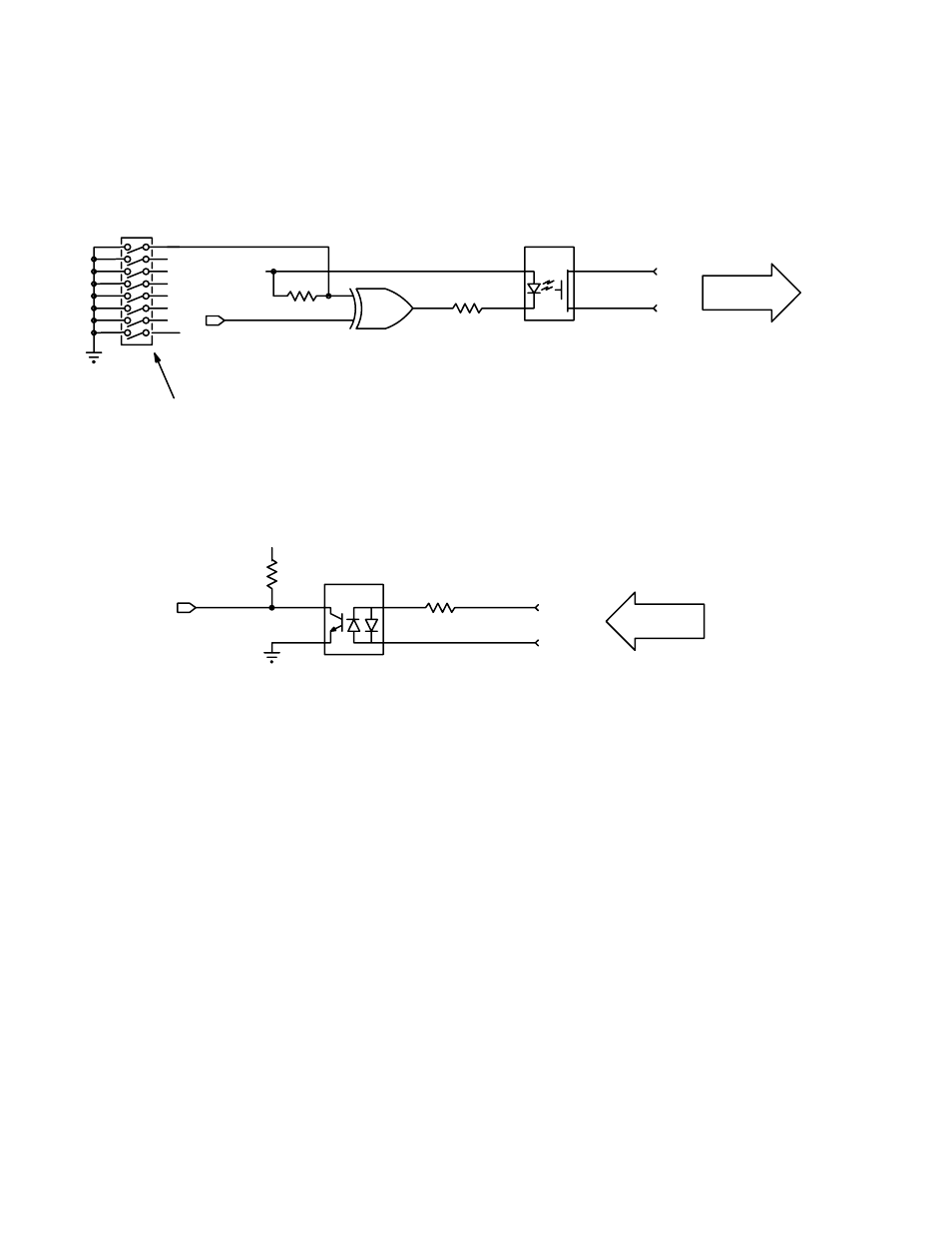
Figure 2−137. MI/MC 3040 optoelectronic relay circuit (example). For discussion, see page 2−123.
2
U16
from external
device
Figure 2−138. MI/MC−3040 optical coupler status circuit (example). For discussion, see page 2−123.
+5V
R137
10K
OPTO (31)
4
3
1
2
U69
PC314
(TM2)
R89
2K
STB (31)
STA (31)
J1−B8
J1−B9
This manual is related to the following products: