Replacing a failed unit – Grass Valley VM 3000 System Controllers v.7.4 User Manual
Page 711

Redundant VM/SI
K−3
VM 3000 Installation and Operating Manual
Each VM/SI has a unique PROM−stored hardware address that is normally entered on the Network Devices table. How-
ever, when rapid replacement of a failed unit is desired it is better to use user−defined addressing; this allows a replace-
ment unit’s address to be made identical to that of a failed unit and installed with a minimum of disruption to the system.
User−defined addressing is accomplished using rotary DIP switches S2 and S3 (as discussed on page 2−53). For the
“emergency replacement” application, Grass Valley suggests that these switches be set initially as follows:
Switch S3
Switch S2
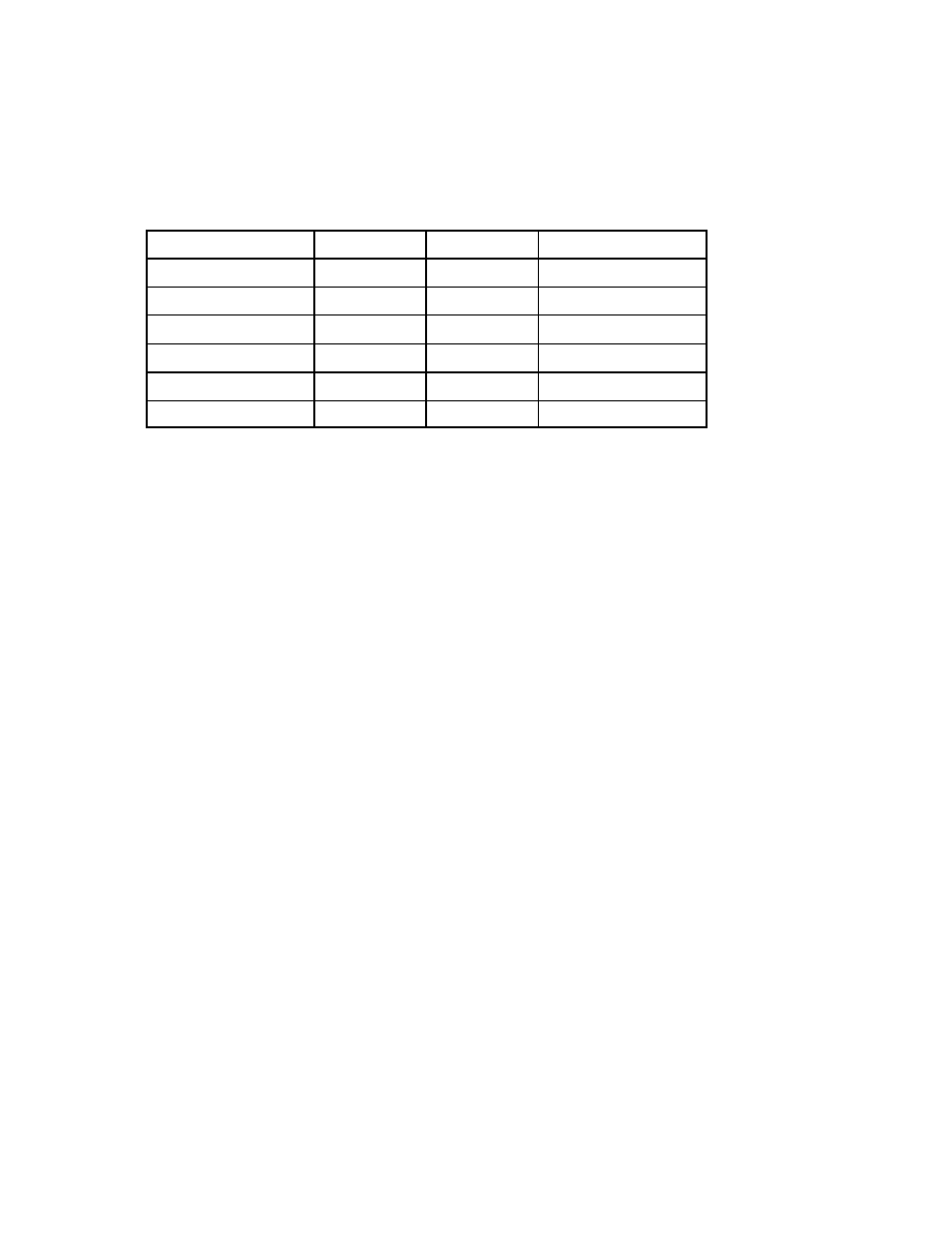
Resulting Address
Primary VM 3000
0
1
0080CEDEAD01
Backup VM 3000
0
2
0080CEDEAD02
Primary SI 3000
0
3
0080CEDEAD03
Backup SI 3000
0
4
0080CEDEAD04
Replacement VM 3000
1
1
0080CEDEAD11
Replacement SI 3000
1
2
0080CEDEAD12
Table K−3.
In the example system shown in Figure K−2, the primary VM would be set to “01,” the backup VM to “02,” and the replace-
ment VM to “11.” The “Resulting Address” shown in Table K−3 would be entered in the Network Description table. It’s a
good idea to clearly mark the addresses on the outside of the Primary and Backup units.
2.
Pre−load the system software into the replacement VM/SI.
“System−loading” means that the replacement unit always has a copy of the current system files. The easiest way to
maintain this condition is to leave the unit on the LAN at all times. Whenever a new version of Jupiter software is down-
loaded to the Primary and Backup VM/SI units, the replacement unit will be updated automatically. This is the recom-
mended procedure.
It is also possible to connect the replacement unit to the LAN only long enough to receive new system software and then
place it in storage (i.e., powered down and disconnected). The unit’s flash memory is designed to retain the system soft-
ware without external power for many years.
Replacing a Failed Unit
A fault condition should be indicated by a red fault light on the front panel, or, in the case of a failed power supply, no lamps
illuminated. Control should have switched to the other VM/SI by this point. Check that it has by looking for the green Active
lamp. Then proceed as follows:
1.
De−power the faulty VM.
De−powering a VM should automatically cause a switch to the other working unit within about 15 seconds.
2.
Disconnect the faulty unit, noting cable positions.
Note 1: When removing the LAN cable from the faulty unit, be sure to maintain LAN integrity and termina-
tion; i.e., check that the LAN cable is still connected to the working unit with a 50 Ohm terminator at each
end.
