Installing control panels, Connections t0 vm/si 3000 – Grass Valley VM 3000 System Controllers v.7.4 User Manual
Page 122

Hardware Installation
2−50
VM 3000 Installation and Operating Manual
Installing Control Panels
CONNECTIONS T0 VM/SI 3000
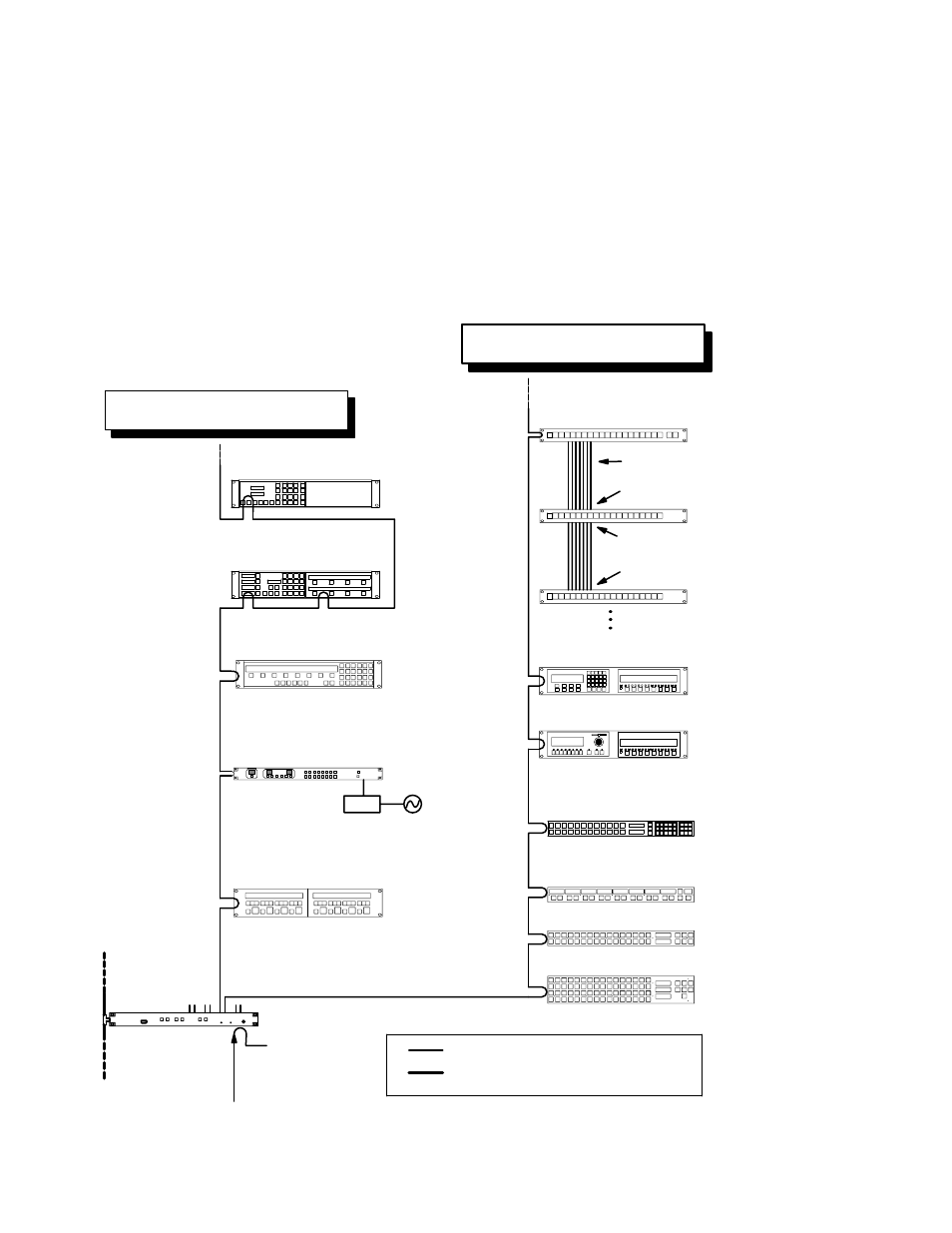
For VM/SI 3000, the protocol for the serial ports must be set in pairs. (The protocol is set at the file server, as described later
in this manual.) In the example shown in Figure 2−58, port 5 is connected to MPK devices (control panels). Notice that be-
cause the port protocol is set in pairs, port 6 must also be used with MPK devices.
Figure 2−58. Control panel connections to VM/SI 3000.
VM/SI 300
(VM 3000 shown)
Serial (MPK) bus
CP 3000 Switcher Control
with expansion panel
MC 3000 Machine Control with
expansion panel
CP 3020 Push Button Control Panel
Serial data cable (see page 2−109)
Sync ref. See
CP 3021 Push Button
Expansion Panel
12 in. ribbon cable supplied with CP 3021
“Input” connector
“Input” connector
“Output” connector
CP 3021 Push Button
Expansion Panel
4 CP 3021 max.
MC 3010/2 Dual 4−Machine
Control Panel
CP 300 Series Control Panel
Serial (MPK) bus
PS−20
110 V only. See page 2−51.
CP 3800 Control Panel
CP 3808 with CP 3809 expansion panel
CP 3830 Control Panel
For recommended max devices see VM/
SI 3000 Bus Loading on page 1−18
For recommended max devices see VM/
SI 3000 Bus Loading on page 1−18.
CP 3864 Control Panel
CP 3832 Control Panel
CP 3810 Control Panel
Note: CP 3800 cannot connect to SC 3000.
CP 3824 Control Panel
